Beams
The frame "Beams" contains a table with the list of beams. Adding beams is performed in the "New Beams" dialog window.
The beam location is selected from the combo box (mesh line, terrain segment).
Added beams can also be edited on the desktop with the help of active objects. The program employs the following coordinate systems.
The beam elements serve to model beams, linings, sheeting walls, etc. Distribution internal forces such as moment, normal and shear forces developed along a beam axis can are derived from the beam element end forces.
Beams are assigned to already defined lines (free lines, terrain segments) - the corresponding line then represents the beam axis.
It is also possible to enter so-called fictitious beams.
The program offers several basic types of cross-sections. Nevertheless, the user is free to introduce the required cross-section independently.
An important step when modeling beams is the definition of contact elements characterizing the interface behavior between the beam and the soil. Contact (interface) elements can be assigned to both sides of a beam. A correct definition of contacts is essential especially when modeling sheeting walls.
Types of endpoints connections can be specified for each beam.
In subsequent stages, the beam can be either strengthened or degraded.
The program automatically includes the beam self-weight into the analysis. This feature, however, can be turned off when defining the beam.
Beams are modeled using the beam elements with three degrees of freedom at each node.
The beam elements are formulated on the basis of the Mindlin theory. The theory assumes that the plane cross section normal to the beam axis before deformation remains plane after deformation but not necessarily normal to the deformed beam axis. At present, the internal forces are evaluated at the element nodes and from the beam end forces.
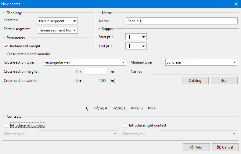 Dialog window "New beams"
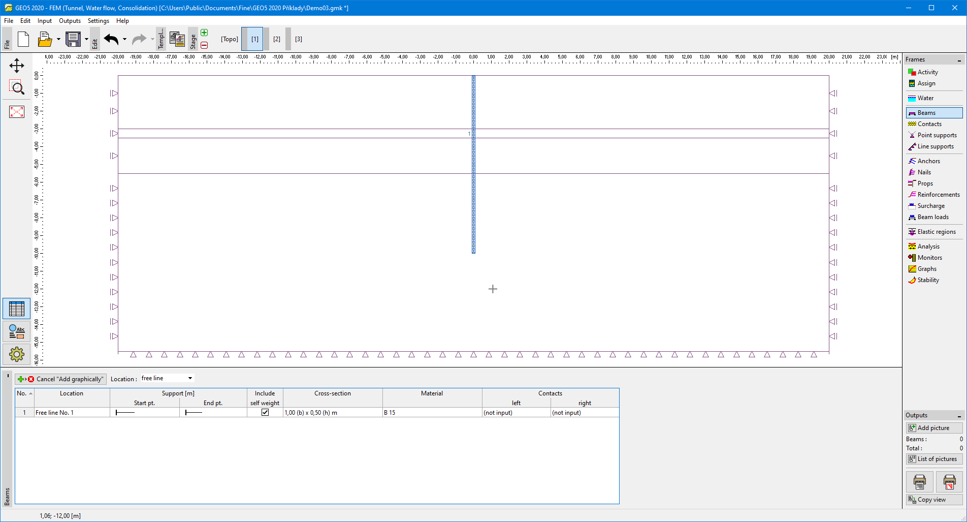 Frame "Beams"