Approach According to Masopust
The load-settlement curve of a single pile is constructed in the following way:
1) The ultimate skin friction qs is determined as follows:
![]()
where: | a,b | - | |
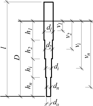
vi | - | depth from terrain up to the middle of the ith layer [m] | |
di | - | pile diameter in the ith layer [m] |
and pile skin bearing capacity is provided by:
![]()
where: | m1 | - | |
m2 | - | ||
di | - | pile diameter in the ith layer [m] | |
hi | - | thickness of the ith layer [m] | |
qsi | ultimate skin friction in the ith layer [MPa] |
2) The pile base bearing capacity qb follows from:
![]()
where: | e, f | - | |
D | - | pile length inside soils [m] | |
db | - | pile base diameter [m] |
3) The proportion of applied load transferred to pile base β is written as:
![]()
where: | qb | - | pile base bearing capacity [MPa] |
| - | weighted average of ultimate skin friction [MPa] | |
D | - | pile length inside soils [m] | |
db | pile base diameter [m] |
The load at the mobilization of skin friction Rsy is then given by:
![]()
where: | Rs | - | pile skin bearing capacity [N] |
β | - | proportion of applied load transferred to the pile base [-] |
4) The load at the shaft resistance activation (= mobilization of skin friction) Rsy is given by:
![]()
where: | Is | - | |
Rsy | - | load at the mobilization of skin friction [N] | |
d | - | pile diameter [m] | |
Es | - | secant modulus of soil along the pile shaft [MPa] |
5) The load at the pile base for the prescribed settlement (for limiting settlement of 25 mm) follows from:
![]()
where: | β | - | proportion of applied load transferred to the pile base [-] |
Rsy | - | load at the mobilization of skin friction [N] | |
slim | - | limit settlement (usually prescribed as 25 mm) [m] | |
sy | settlement at shaft resistance activation [m] |
and the pile resistance attributed to a given limit settlement slim is then provided by:
![]()
where: | Rb,lim | - | load on the pile base for prescribed settlement [N] |
Rs | - | pile shaft resistance [N] |
 Approach according to Masopust
Literature:
Masopust, J.: Vrtane piloty. 1st edition, Prague, Cenek a Jezek, 1994, 263 p.
Masopust, J., Glisnikova, V.: Zakladani staveb Modul M01. 1st edition, Brno, AN CERM, 2007, 182 p., ISBN 978-80-7204-538-9.