Member properties
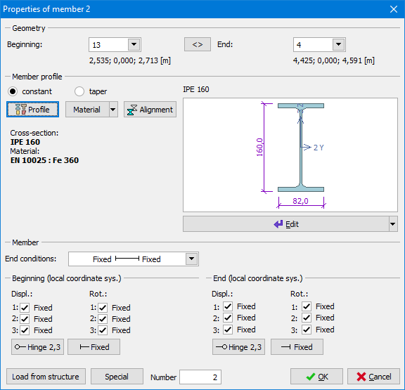
This window contains basic properties of member: beginning and end joint, cross-section, material and end conditions. The button "Special" in the left bottom corner launches the window "Special properties of member", that contains advanced properties (subsoil parameters, excluded tension or compression, spring end connections).
The position of the member is given by the numbers of beginning and end joints. These joints can be changed with the help of the list box or by the direct input of the number on the keyboard. The button "<>" changes the member orientation (switches the beginning and end joint), the positions of relative joints and loads are preserved.
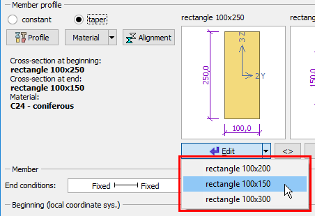
The frame "Member profile" contains properties of cross-section and material. The member may have identical cross-section along the whole length (option "constant") or the cross-section vary along the member length (the option "taper"). The cross-section and material can be changed in the window "Edit profile" which can be launched by the button "Profile". Parameters of the existing cross-section (e.g. dimensions) or material can be changed in the windows "Cross-section editor", (the button "Edit" under the cross-section view) or "Materials catalogue" (the button "Material"). Members with variable cross-section have two buttons for cross-section edit, the first one for member beginning and the second one for member end. Buttons for edit of cross-sections and materials contain drop down menu with existing cross-sections and materials. These list can be also used for fast input of these properties.
 List of existing cross-sections
The visual appearance of the structure can be modified by an alignment of the member which can be specified in a dedicated window using the button "Alignment". This alignment defines the position of member mass relatively to reference line of the member. It affects only structure view not the analysis.
The frame "Member" contains the choice of end conditions (pinned, fixed):
|
|
|
|
|
|
|
|
|
|
The end conditions can be also specified with the help check boxes "Fixed" for corresponding directions or rotations. The end conditions are specified in the local coordinate system of member.
Parameters (cross-section, material, end conditions) may be copied from existing member using the tool "Load from structure".
Pinned connection
The rotation about the member axis (local axis 1) should be considered when entering pinned end conditions on both ends of member. Completely pinned connection (no rotation fixed on both ends) causes singularity during analysis and collapse of the calculation. Therefore, rotation about the local axis 1 should be fixed at one end of a member. Such solution ensures analysis stability and does not cause torsional stiffness of the member. This solution is not necessary in cases, where the rotation about the axis 1 is prevented by another connected member.
End conditions are also described in the theoretical chapter "End conditions".
 Window "Properties of member"