Program Fin 2D
The program "Fin 2D" is suitable for the structural analysis of 2D truss and frame structures with the help of finite element method. The particular members of the structure may be designed in the verification programs.
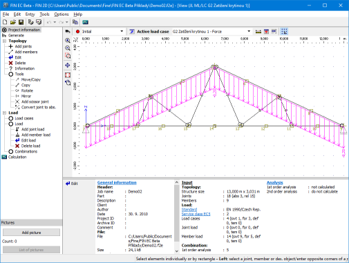
The main parts of the user interface are the workspace, the tree menu, the main menu and the input frame in thee bottom part of the window. Tools for documents printing are organized in the window "Print and export document", which can be opened using the printing icon in the toolbar "Files" or using the appropriate link in the part "File" of the main menu.
Tree menu
The tree menu is the fundamental navigation object of the program. It contains all important functions for the work with the structure. The tree menu contains these parts:
- Topology - Contains tools for input of structure topology (joints and members)
- Load - Loads, load cases and combinations can be specified in this part
- Calculation - Runs the calculation of internal forces
- Results - Shows the results and contains tools for verification of members
The bottom part of tree menu contains buttons for insertion and administration of pictures for output documentation. The structure view in the workspace may be saved and used in output documentation. The pictures are updated continuously, the pictures in the documentation shows the latest state of structure including corresponding results. The new picture can be added with the help of the button "Add picture". After using this button, the window "Picture properties" appears. The parameters like description, orientation and position in document structure can be defined in this window. The pictures can be modified in the window "List of pictures", that can be opened by the button of the same name.
Workspace
The workspace shows the created structure and can be used both for the graphical input and results display. The displayed items can be switched on or off in the window "Drawing settings", that can be launched by the button "![]() " in the toolbar above the workspace. The view configuration may be saved or restored with the help of pre-defined templates, the work with templates is described here.
" in the toolbar above the workspace. The view configuration may be saved or restored with the help of pre-defined templates, the work with templates is described here.
 Choice of view template
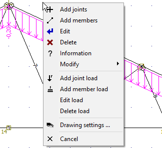
The workspace also contains an option to use context menus, that can be opened by right mouse button click. This menu contains the most common commands. The range of commands differ according to the element type. Menus are different for joints, members and general point in the workspace. Additional commands are available for structures with selected elements (highlighted by green in the workspace).
 Context menu for general place of the workspace
Main menu
The main menu contains complete range of available tools and functions, it may substitute the work with the tree menu. Additionally, the main menu contains part "Tools" with some useful tools.
Input frame
The input frame is located in the bottom part of the window. The default view shows the general information about the project (number of members and joints, load cases etc.), status of analysis and also project details specified in the window "Project information", that may be used in the heading or footing of the documentation. This window can be opened with the help of the button "Edit".
 Main application window