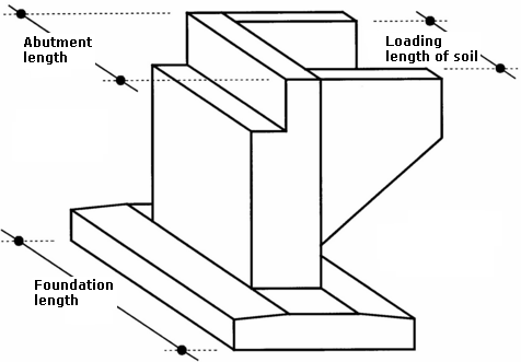
Calculating Abutment Forces
An abutment is analyzed per 1 m (1ft). All forces entering the analysis are therefore adjusted in the program as follows:
- the abutment self-weight, assumed per 1 m (1ft), is calculated from the input transverse cross-section
- reactions inserted by the bridge and the approach slab are input in kN (kpi) using the values for the entire abutment, these values are in the analysis divided by the abutment length
- soil pressure is determined per 1 m (1ft) and then multiplied by the ratio length of load due to soil / abutment length,
- weight of soil wedges is determined per 1 m (1ft) and then multiplied by the ratio length of load due to soil / abutment length,
- surcharge is determined per 1 m (1ft) and then multiplied by the ratio length of load due to soil / abutment length,
- input forces and front face resistance are assumed per 1 m without reduction
- wing walls - the wing walls self-weight is computed from their geometry; before introduced in the stem design and foundation verification it is divided by the abutment length (it is the user's responsibility to either include or exclude the effect of wing walls in from the analysis).
Computation of individual abutment forces is described in more detail in the chapter "Wall analyses".
All forces acting in the foundation joint that are introduced in the verification analysis (except for the front face resistance) are multiplied by the ratio abutment length / foundation length.
 Geometry of bridge abutment