Transient Flow Analysis
The actual analysis proceeds in two and more stages ("Water flow"), where the first stage serves to set the initial conditions, i.e. the distribution of initial pore pressure, initial pressure head, degree of saturation, and relative permeability at the onset of transient flow analysis. Several options are available to set the initial pore pressure:
- With the help of a groundwater table
- Directly with the help of pore pressure interfaces
- Running the steady-state flow analysis
The first option assumes a hydrostatic (linear) distribution of pore pressure over the height. Below GWT the program generates positive pore pressures, whereas above GWT the negative pore pressures (suction) are generated. The second option allows for considering a dry soil by prescribing e.g. negative pore pressures over the entire infiltrated region. The third option requires running the steady-state analysis. Based on the assigned material model the program then determines the initial degree of saturation and relative permeability as a function of the initial pore pressure. Figure 1 shows the distribution of initial pore pressure provided by steady-state analysis for the assumed hydraulic conditions. Clearly, only the pressures below GTW are presented. The initial state in an unsaturated or partially saturated region can be partially judged by plotting, for example the distribution of initial degree of saturation as seen in Figure 2. When selecting the "No water" option the initial pore pressure values are set equal to zero.
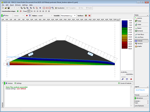 Figure 1 - First calculation stage: Distribution of initial pore pressure
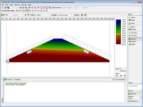 Figure 2 - First stage: Distribution of initial degree of saturation
The transient flow analysis is performed from the second stage on where the next stage follows the preceding one. Each stage requires setting the analysis time, time-dependent variation of boundary (hydraulic) conditions, and the time step length. The current version of the program allows us to either introduce the entire load at once at the beginning of the calculation stage or to assume that it linearly increases with time during the course of stage calculation ("Water flow"). In the first case, the initial time step is set to 1/10 of the assigned time step. Next, the calculation continues with the assigned time step. It is reasonable to adjust the time step during the course of analysis. A shorter time step is recommended at the beginning of the analysis. With longer times, when the solution approaches the steady-state conditions, the time step can be increased considerably (e.g. from 1/10 of the day, up to several days). Figures 3 and 4 display an intermediate state and a steady-state solution, respectively, corresponding to a sudden increase of GWT in the second calculation stage. Figures 5 and 6 show similar states associated with a subsequent rapid drawdown simulated by resetting the original level of GWT at the seventh calculation stage.
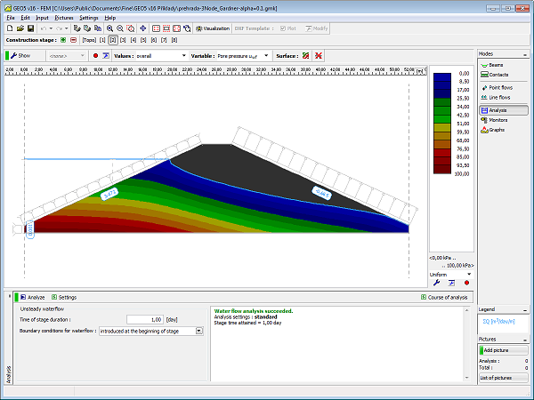 Figure 3 - Second calculation stage: Distribution of pore pressure at a given time of analysis
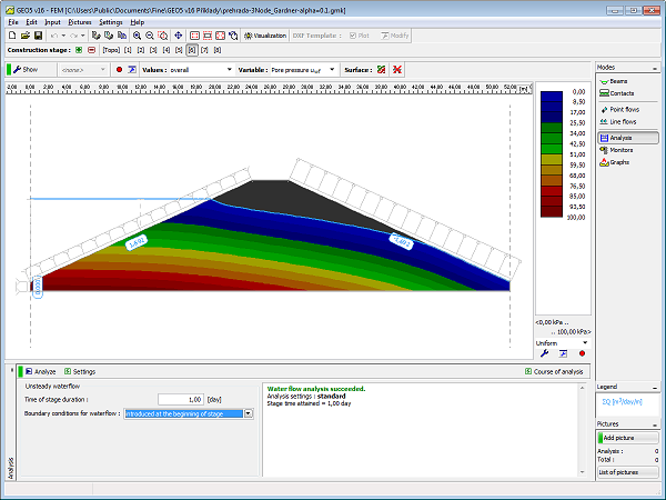 Figure 4 - Sixth calculation stage: Distribution of steady-state pore pressure
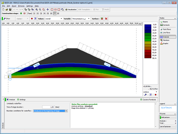 Figure 5 - Seventh calculation stage: Distribution of pore pressure at a given time of analysis
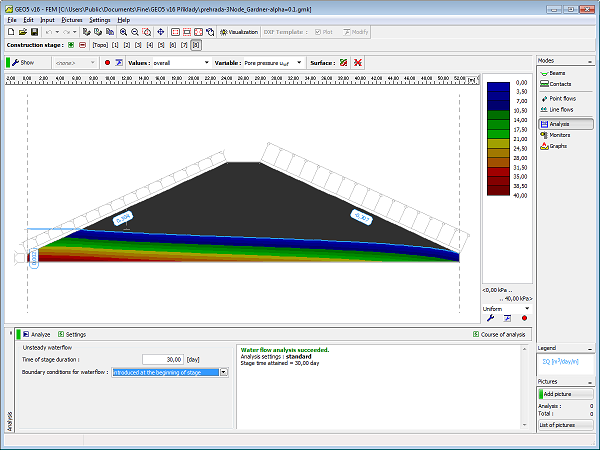 Figure 6 - Eighth calculation stage: Distribution of steady-state pore pressure