3D structure
Introduction
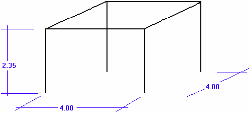
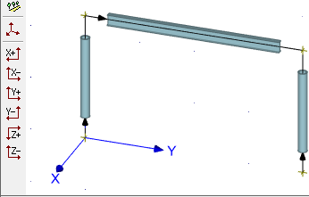
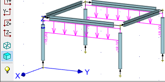
This tutorial shows the input and verification of the structure shown in the picture below. Columns are made of RHS profiles, beams are I-profiles. Material class Fe 360 is used. Beams are loaded by linear load 18 kN/m. Two columns are loaded by trapezoidal load (12kN/m at the top and 19kN/m at the bottom). Supports are rigid. The programs "Fin 3D" and "Steel" will be used.
 Structural model
The main window appears after running the program "Fin 3D".
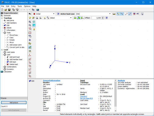 Main application window
Basic part of structure
The structure will be created with the help of manual input of joints and members. This input style shows most of particular procedures which appear during the work with the software. The input will be done using following steps:
- Input of a first frame (two columns and a beam)
- Input of load
- Copy of the existing frame
- Input of transverse beams and their load
This procedure is not the easiest way, however, it shows variety of functions and tools included in the software. First, we save the project. The name (for example "3D project") appears in the heading of the window and is also copied into designing modules.
We select the mode "Add members".
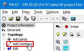 Mode for input of members
This mode launches the window "Member prototype". This window contains properties (cross-section, material, end conditions) that will be assigned to new members. We will continue with the help of the button "Profile".
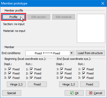 The button for input of cross-section and material
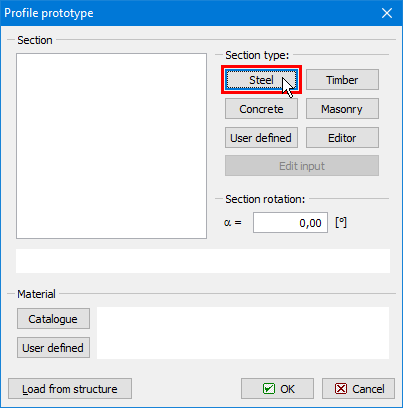
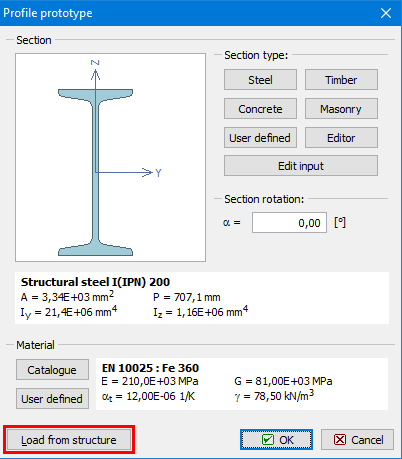
The window "Profile prototype" which contains options for input of cross-section and material. We will use the button "Steel".
 The button for input of steel cross-section
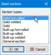
The window "Steel section" that appears after the clicking on the button contains an option to select type of cross-section. We select database of rolled cross-sections (the option "Solid hot-rolled") and open the window "Profiles catalogue" by pressing the button "OK".
 Choice of cross-section type
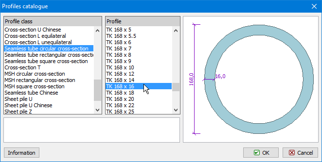
We select the section type "Seamless tube circular cross-section" (RHS) in the first column of the database and the item "TK 168x16" in the second column. The choice of cross-section has to be confirmed by the button "OK".
 Database of cross-sections
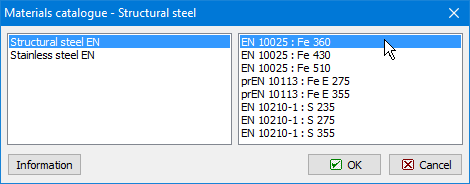
After the confirmation a window with material grades appears. We select the strength class "EN 10025: Fe 360".
 Choice of strength grade
The properties entered in the window "Profile prototype" are displayed in the following figure.
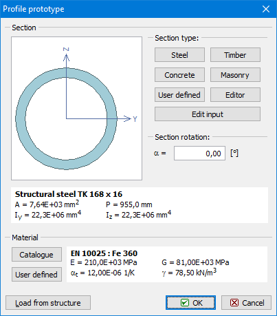 Profile prototype with specified cross-section
After the confirmation of the window "Prototype profile" by the button "OK", the prototype properties will be docked in the bottom frame. The input of members in the workspace is enabled now. First, we will insert a column. We specify the start of global coordinate system as a member beginning. The cursor snaps to this points automatically in close surrounding. The snapping is also indicated by the change of cursor appearance.
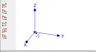 The cursor appearance when snapping to beginning of coordinate system
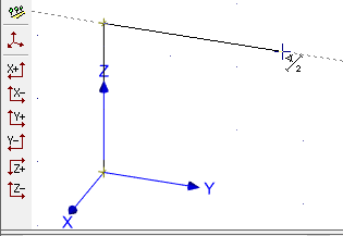
We show the orientation of the column by the cursor in the next step (the orientation should be in the direction of the axis "Z"). The alignment into this direction is automatically offered by the program (the program automatically snaps into 45° directions as a default).
 Member orientation given by the position of the cursor
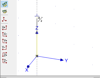
Paralelly, we specify the length of member (column height) 2.35 using keyboard. The lengths have to be specified in metres. The length entered on the keyboard is automatically inserted into the input field "Δr" in the bottom part of the tree menu. The input has to be confirmed by the button "Enter".
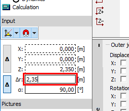 Input of member length
The input of beam follows. The beginning is identical to the end of the column, the end will be specified with the help of cursor (direction parallel to the axis "Y") and the length 4m. We will finish the input of the length by the button "Enter".
 Input of beam
We will continue with the input of the second column. The input will be done from the end of the beam against the direction of the axis "Z".
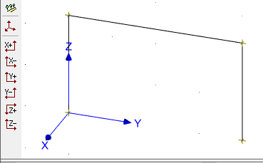 Frame made of two columns and a beam
We terminate the input of members by a right mouse button click. After that, we change the display settings to improve the visibility of input. The window "Drawing settings" can be opened with the help of the context menu, which can be launched by a right mouse button click everywhere in the workspace.
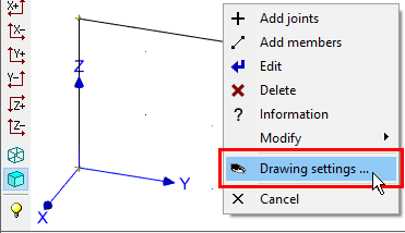 Drawing settings in the context menu
The window "Drawing settings" contains parameters, which affect the displayed objects in the workspace. We check settings "Beginnings" and "Sections". First setting highlights beginnings of members by black arrows, second shows member masses. The window has to be closed by the button "OK".
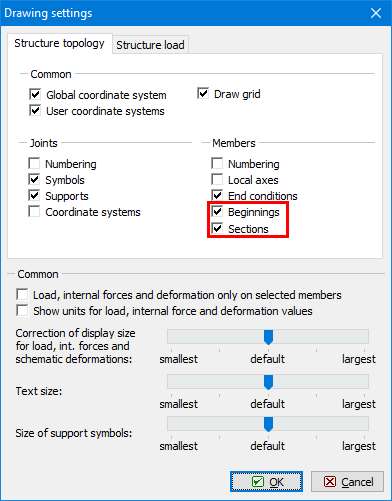 Changes in the window "Drawing settings"
The workspace shows now, that both columns and beam have identical cross-section (RHS). Therefore, next step is to change the cross-section of the beam. We open the context menu for the beam by right button mouse click on this member. We select the option "Edit member" in this menu.
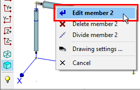 The context menu for the beam
This action opens the window "Properties of member". We change the cross-section using method already described above. The button "Profile" launches the window "Edit profile". We select the option "Steel" in this window.
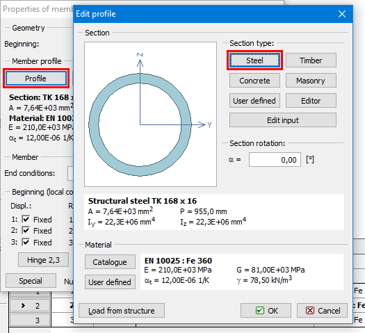 The change of beam cross-section
The cross-section type "Solid hot-rolled" should be selected for opening the database of rolled cross-sections. The beam should have the cross-section "I(IPN) 200".
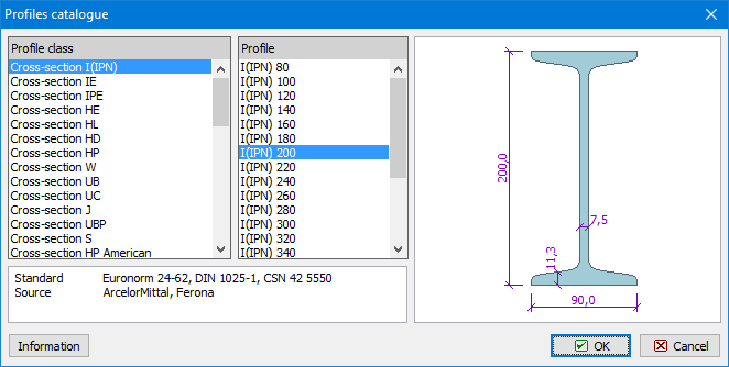 Cross-section of beam
After finishing the changes of beam's cross-section, we will continue by modifying the second column. We open the window "Properties of member 3" for the right column and change the orientation of the member (the order of start and end joints). The orientation is not significant for an analysis of internal forces, however, may be critical for a correct verification in the designing module when using unsymmetrical design properties (parameters of buckling etc.). The orientation can be changed by the button "<>" between numbers of beginning and end joints. The weindow has to be closed by the button "OK".
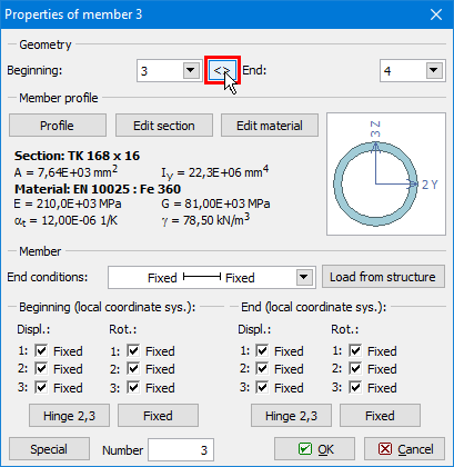 Change of column orientation
After that, both columns have identical orientation parallel to the axis "Z".
 The structure with identical orientation of columns
Load input
The input of loads follows. We switch the tree menu into the mode "Load cases" and add new load cases with the help of the button "Add" in the toolbar, that is located on the left side of the input frame.
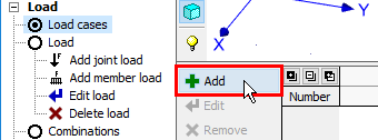 The button for insertion of new load cases
The window "New load case" automatically starts with properties of the load case "Self weight - permanent". This load case represents a self weight of the structure and the loads included in this load case are generated automatically according to the member properties. We insert this load case by the button "Add".
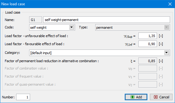 Load case "Self-weight"
Analogously, we add two other load cases with selected type "Long-term variable".
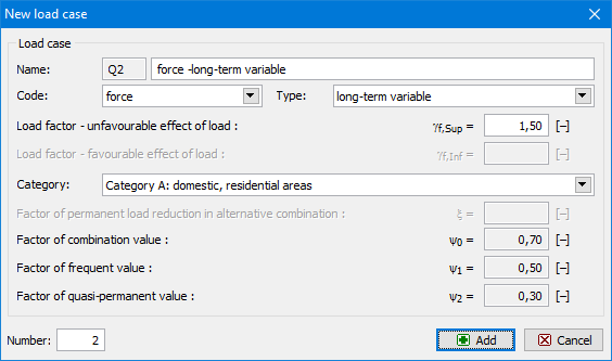 Properties of long-term load case
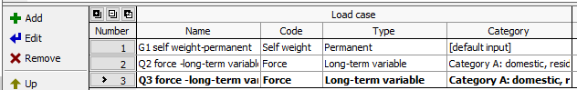
The list of specified load cases is displayed in the bottom frame.
 List of load cases
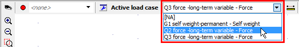
The next step is to insert loads into these load cases (except self weight). The active load case (we start with "Q2") has to be selected in the drop-down menu in the heading of the workspace.
 Choice of the active load case
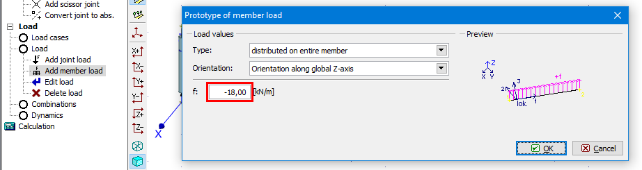
We switch the tree menu into the mode "Add member load" and specify linear load with the value -18 kN/m in the window "Prototype of member load". The prototype properties has to be confirmed by the button "OK".
 Prototype of member load
We assign this load to the beam by clicking on the member in the workspace. The load appears in the workspace immediately.
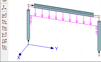 Structure with inserted load
We change the active load case to "Q3" in the heading of the workspace. As the load will be identical for both columns, we will use a tool for insertion of loads to selected members. First, we select columns in the workspace. Selected members are highlighted by a green colour. After that, we select the option "Add member load" in the context menu.
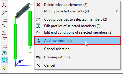 The context menu for columns
We select the load type "trapezoid on part of member" and the orientation "Along global X-axis". We also specify values at the beginning and end and the length.
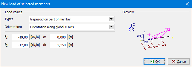 Load for columns
The load is applied to both columns after the confirmation by the button "OK". The selection of columns can be cancelled by the key "Esc".
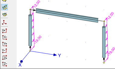 The structure with column loads
The last part of the load input is a creation of combinations. The combinations are organized separately for ultimate and serviceability limit states in the program. First, we specify combinations for ultimate limit states. We will create two combinations. Both of them will contain all three load cases, however, the main variable load will differ. The tree menu has to be switched to the mode "Combinations". We add new combinations with the help of the button "Add" in the tab"1st order combination ULS" in the bottom frame.
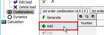 The button for input of load combinations
Combination properties are organized in the window "New combination". Load cases can be added into the combination with the help of the left check boxes in the column "Consider" of the table, which can be found in the mid part of the window. We also tick the second check box for the load case "Q2" in the column "Consider". This setting sets the load case "Q2" as main variable load. We insert the combination into the project with the help of the button "Add".
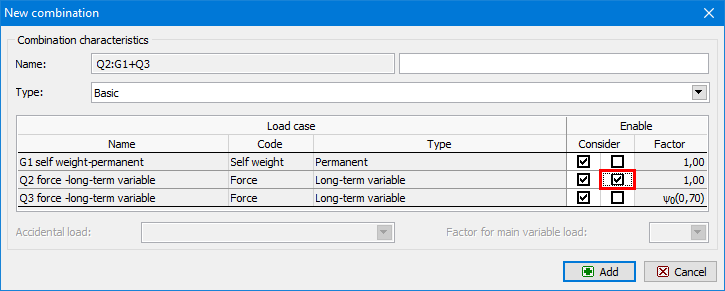 The main variable load
We change the setting in the second column "Consider" and set the load case "Q3" as main variable load. Again, this new combination has to be added by the button "Add". We close the window by the button "Cancel". Created combinations can be displayed in the dedicated window "Table of combinations". This window can be opened with the help of the button "Table" in the toolbar on the left side of the bottom frame.
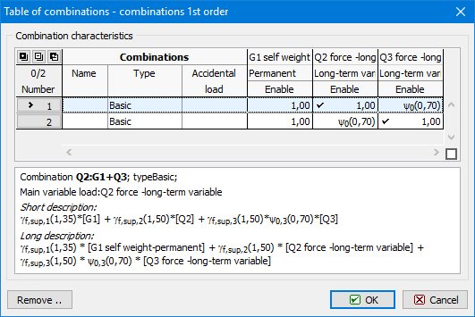 Table of combinations
The input of combinations for serviceability limit states follows. We will use an automatic tool "Generator of combinations" in this case. This tool can be opened by the button "Generate" in the tab "1st order combination SLS".
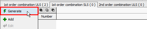 The button for generating of combinations
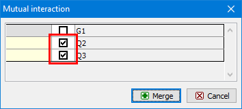
The window "Generator of combinations" contains rules, which affect the count of created combinations. We add a new rule which ensures, that specified variable load cases will be included in combinations together. We will use the button "Create" for the table "Mutually interacting load cases".
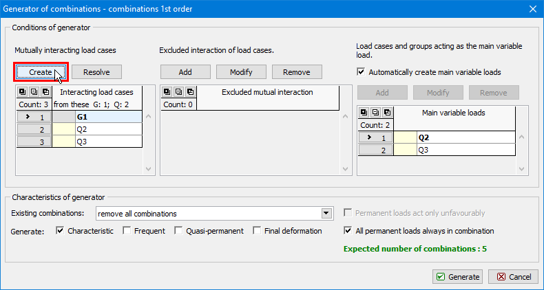 The button for input of interacting load cases
We tick load cases "Q1" and "Q2" in the window "Mutual interaction" and insert this rule by the button "Merge".
 Mutual interaction of load cases
Other parameters of generator may stay unchanged. The tool creates a set of combinations for serviceability limit states after closing the generator window by the button "Generate".
Enlargement of structure
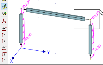
This chapter describes the enlargement of the structure with the help of tool for copying the elements. This tool will copy existing frame to a new position. First, we select upper joints, as transverse beams can be created automatically in the positions of selected joints.
 Selection of joints in the workspace
We use the tool "Copy" in the tree menu and select the mode "Move in axis direction".
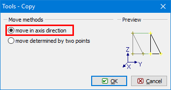 The choice of vector input
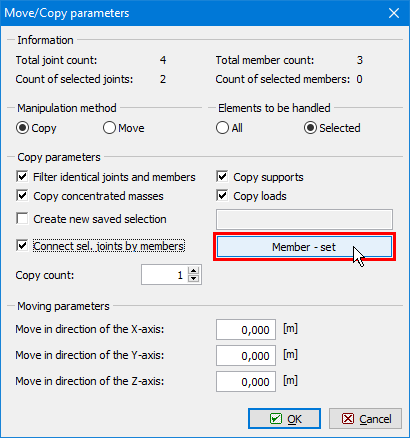
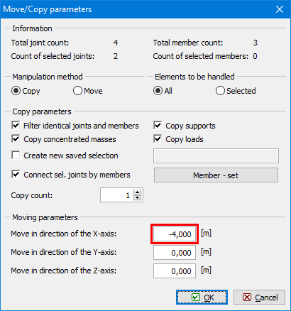
The settings in the window "Move/Copy parameters" should be defined according to the figure below. We use also the setting "Connect sel. joints by members", which creates new beams connecting old and new frames in selected joints. The cross-section of these members has to be set with the help of the button "Member - set".
 The button for input of connecting beams properties
The known window "Profile prototype" appears. It is possible to use the button "Load from structure" in the left bottom corner and copy cross-sectional properties from existing member.
 The button for copying properties
The last part of copy properties is the vector of transformation. We enter the value -4m into the input line "Move in direction of the X-axis". The parameters have to be confirmed by the button "OK".
 Input of vector
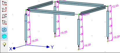
The tool copied the frame into a new position and also added new beams connecting old and new frame.
 Created structure
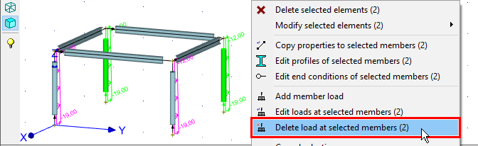
Columns were copied including loading. As only two columns should be loaded, we have to delete loads on new columns. We select these columns and use the tool "Delete load at selected members" in the context menu.
 Deletion of selected loads
We cancel the selection by the key "Esc". After changing the active load case to "Q2" in the heading of the workspace, the workspace shows, that there is not any variable load pplied to new transverse beams.
 Load case "Q2"
We select these beams and insert loads with the help of the tool "Add member load" in the context menu.
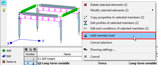 Add load for selected members
The new load properties are identical to existing ones.
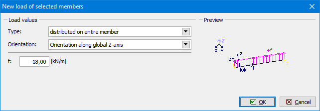 Load properties for new beams
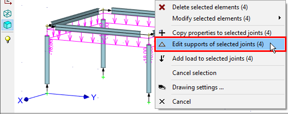
The last topology editing is the input of supports. First, we select all base joints of columns.
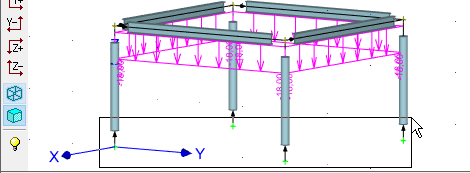 Selection of base joints
We will use the tool "Edit supports of selected joints" in the context menu for selected joints.
 Support properties for selected joints
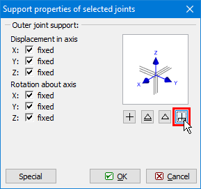
The joinst should be supported in all directions. We can use pre-defined button for fixed support in the right part of the window. The window has to be closed by the button "OK".
 The button for easy input of fixed support
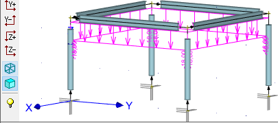
The structure is complete and it is possible to start the analysis.
 Completed structure
Analysis and results
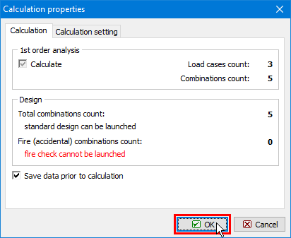
The analysis can be run using the tool "Calculation" in the tree menu. The window "Calculation properties" with analysis parameters appears before the analysis. We start the calculation by the button "OK".
 Confirmation before analysis
The window with analysis log is shown after the calculation is finished. We will go back to the main window with the help of the button "Close".
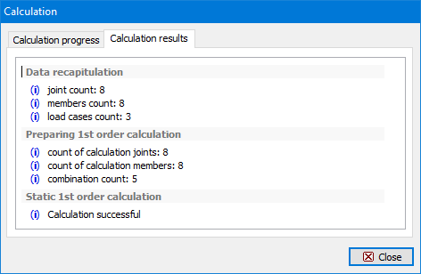 Window "Calculation" with analysis report
The deformed structure appears in the workspace.
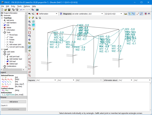 Deformations in the structure
The program contains variety of tools for displaying the results. The window "Results view settings", where the displayed quantities can be selected, can be launched by the button "![]() " in the toolbar above the workspace.
" in the toolbar above the workspace.
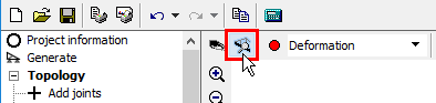 The button for opening window "Results view settings"
We switch on the display of bending moments.
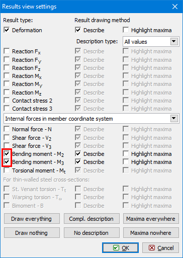 Bending moments
Results can be shown for given load case, combination or envelope. Envelopes show extreme values for more selected load cases or combinations. We will define the envelope of both combinations for ultimate limit states. We select the option "Envelope of 1st order combination, ULS" in the drop-down menu "Diagrams".
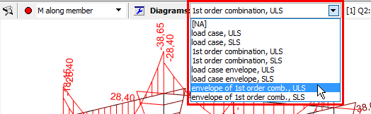 Choice of displayed values
The window "Envelope of 1st order combinations" appears. It is necessary to tick both combinations in the left part of the window.
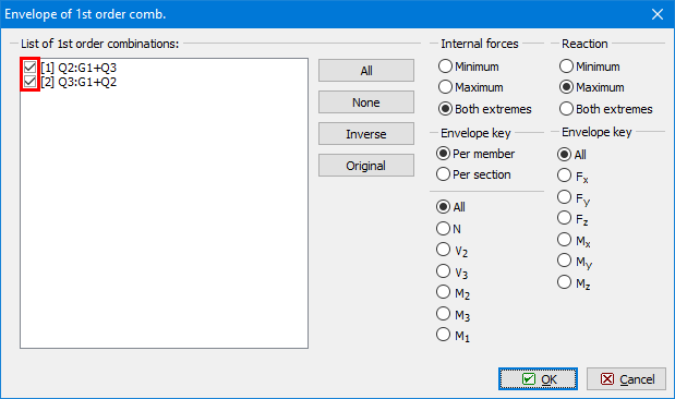 Choice of included combinations
New diagrams show extreme values of bending moments in all points of the structure.
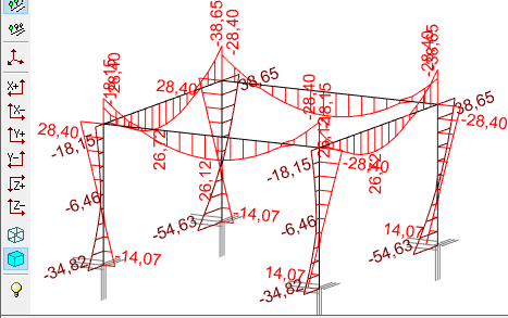 Envelope of bending moments for ULS
Verification
The last part of the work is verification of members in designing modules. To reduce the necessary inputs, we merge eight members into two design groups (columns and beams). Design group is verified as one member, however, more results of analysis are considered during the verification. The design groups can be created automatically using the tool "Design members" "Generate" in the tree menu.
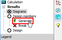 The tool "Generate" in the tree menu
We will use the option "Generate design groups" in the window "Generate".
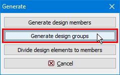 Generation of design groups
The window "Automatic search for design groups" shows, that two design groups (columns and beams) were found. The right part of the window shows the structure view with highlighted active group.
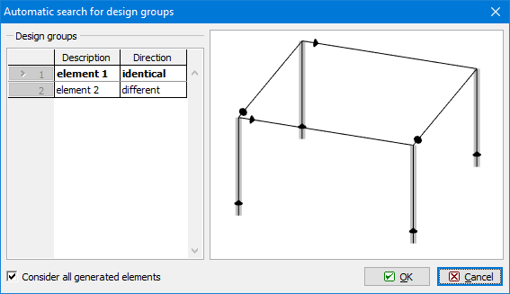 Automatic search of design groups
The warning regarding the different orientation of beams appears after the confirmation of design group search. As beams have symmetrical verification parameters (buckling properties etc.), we can continue using the button "OK".
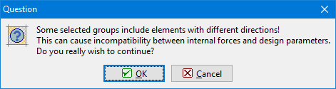 Warning regarding different directions
The created design groups can be described in the bottom frame for the mode "Design members" of the tree menu.
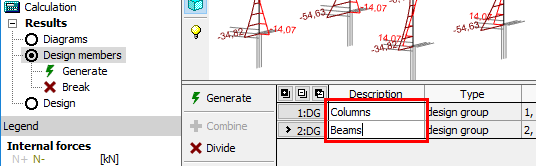 Names of design groups
We switch the tree menu into the mode "Design" and run the design module "Steel" by the button "Run program".
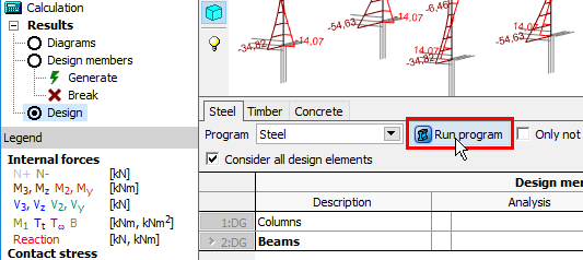 Launching a designing module
All necessary data (geometry, cross-section, material, internal forces) are transferred into the design module. The design members are organized into the tree menu in the left part of the window.
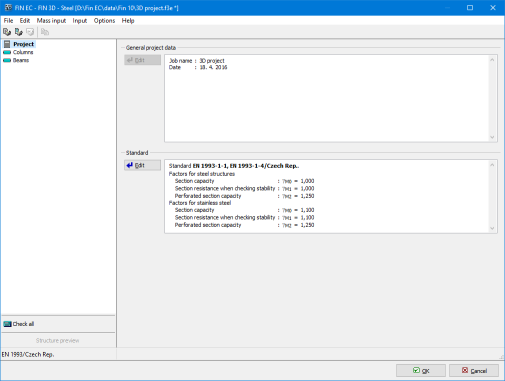 Designing module for steel structures
We switch to the mode "Columns" "Check" and run the verification by the button "Analyse". The program shows warnings, that parameters of buckling and lateral torsional buckling were not set and it is not possible to run analysis.
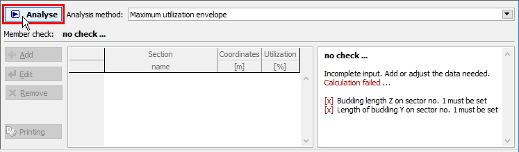 Button for running the analysis
We switch to the part "Buckling" of the tree menu. The parameters can be defined in the bottom frame. As the parameters are constant for the whole length of the column, we will use only default length sector with analysis properties. We will edit it by the button "Edit" in the toolbar on the left side of the bottom frame.
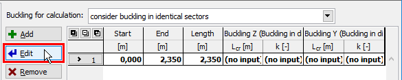 The button for editing buckling properties
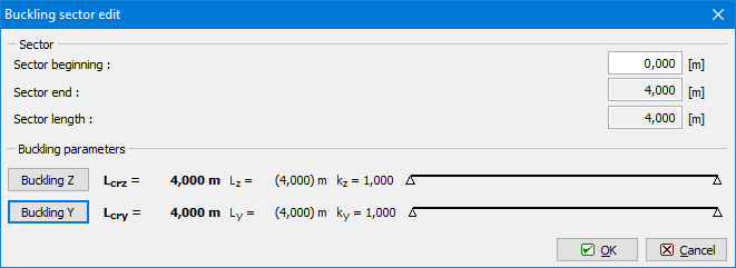
The window "Buckling sector edit" contains buckling parameters for directions z and y. The buttons "Buckling z" and "Buckling y" has to be used for the input. "Buckling z" contains parameters for buckling in the direction perpendicular to the axis z, "Buckling y" parameters for buckling perpendicular to the axis y.
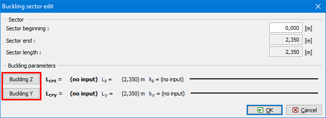 The window "Buckling sector edit"
The buckling length has to be specified in the window "Buckling". To be on a safety side, we will select general end conditions (the button with question marks at ends) and specify value 2.0 for buckling factors "ky" and "kz".
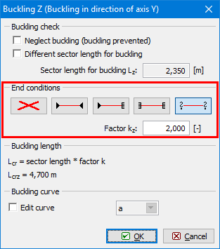 Properties of buckling length
Also shape of bending moment area and end conditions have to be specified for the analysis. We switch to the part "LT buckling" of the tree menu. The parameters of lateral torsional buckling are organized into two tabs according to the bending moments My and Mz.
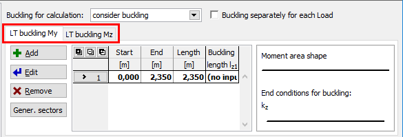 Tabs "LT buckling My" and "LT buckling Mz"
The properties can be edited in the same way as buckling parameters. We specify identical properties for both directions.
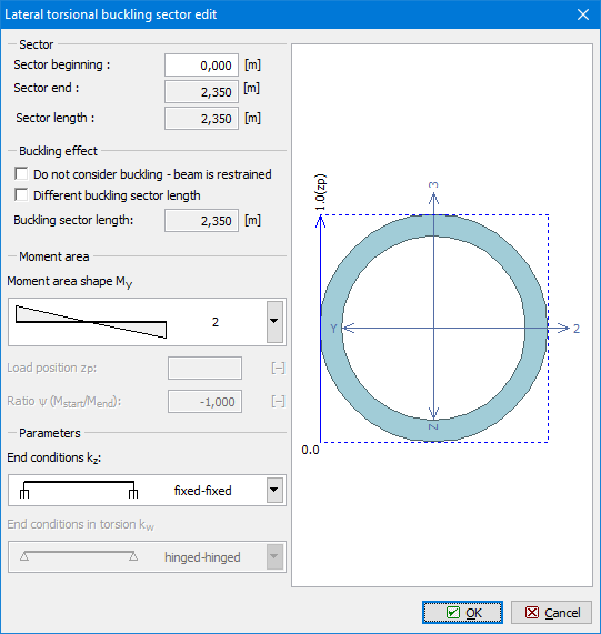 The window "LT buckling sector edit"
We switch back to the mode "Check" and run the analysis again. The results show that the member is OK.
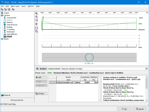 Results for column
The verification of beams follows. The buckling parameters will be specified in the same way as we did for column. Difference is, that we will select pinned end conditions with buckling factors "ky" and "kz" equal to 1.0.
 Properties of buckling sector for beams
The parameters for lateral torsional buckling induced by the bending moment My have to be also specified. The lateral torsional buckling properties are shown in the figure below.
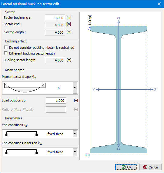 Properties of LT-buckling My
The analysis shows that beams have passed the verification.
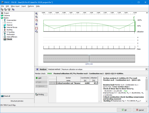 Results for beams
Both design groups are verified. We will close the design module by the button "OK" in the right bottom corner and go back to the program "Fin 3D". The table in the mode "Design" shows the analysis results.
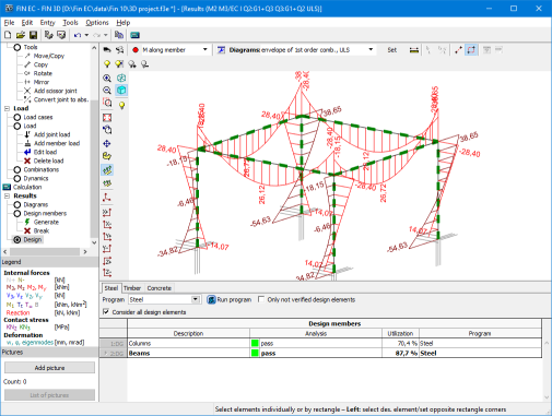 Verified structure