Input elements
Joints may be inserted graphically in the workspace or with the help of the table in the bottom part of the window.
Graphical input
Joints and members can be inserted directly by clicking in the workspace. The tree menu has to be switched into the mode "Add joints" or "Add members".
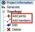 Modes for graphical input of elements
When adding joints, the window "Joint prototype" appears first. This window contains support properties and also input method for relative joints. Two methods are included:
- Relative joint located by mouse click - The position of joint will be determined by the position of cursor.
- Relative joint according to the prototype - The position of joint will be selected according to inputs "Relative joint geometry", which are located in the prototype frame.
The entered data in this window has to be confirmed by the button "OK". After that, the window is docked in the bottom frame.
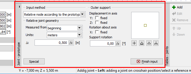 Prototype properties anchored in the input frame
The input is performed by clicking in the workspace. The snapping grid may be used for easier input, the properties of the grid are specified in the window "Options" (main menu part "Tools"). The snapping can be switched off (or switched on) temporarily when pressing the key "Ctrl" during the input. Program offers also snapping points like mid point of member or intersection of two members. Snapping points may be switched on and off in the list, that can be opened by the button "![]() ".
".
The input fields in the bottom part of the tree menu can be also used for the input of joints. It is possible to jump into input fields with the help of cursor or by keyboard entries "y" and "z". For example, the expression y2z1.3 fills 2 into the input line "y" and 1.3 into the field "z".
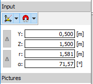 Input fields in the tree menu
The input of members is based on similar procedures. After the selection of an appropriate mode, the window "Member prototype" appears. This window contains properties (cross-section, material, end conditions etc.) that will be assigned to new members. The properties correspond to the parameters in the window "Member properties" (parameters may be copied from existing member using the tool "Load from structure"). Also the window "Prototype of joint", that contains the parameters of newly created joint (beginnings and ends of new members). The data in these windows has to be confirmed by the button "OK". After that, prototypes are anchored in the input frame, where the parameters may be changed.
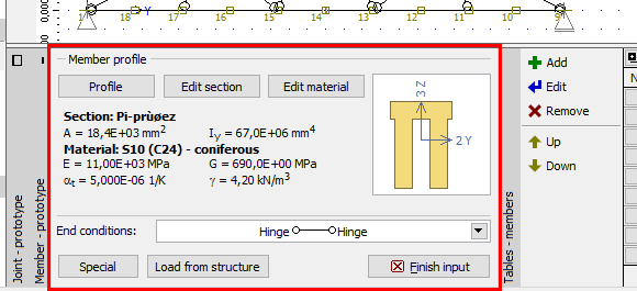 Prototype properties anchored in the input frame
The member input is done by clicking on the position of member beginning and end. The cursor shows number "1" in the mode for input of the member beginning and number "2" in the mode for input of the member end.
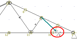 Input of member in the workspace
The member beginning can be entered using methods for joints. The end joint can be specified in a similar way. The easiest way is to specify the member direction by cursor and specify the length on keyboard. The length will be automatically filled into the field "Δr". The input has to be confirmed by the key "Enter". The program automatically snaps the cursor into directions 45°. This behaviour may be changed (switch off or change it to 30°) using the button "![]() ".
".
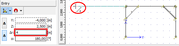 Definition of member direction by the cursor and input of member length with the help of keyboard
Alternatively, it is possible to use snapping to existing joints and snapping points (described above) or extended options of input fields in tree menu. Input fields "Y" and "Z" are usable for the definition of the end point with the help of global coordinates, fields "r" and "α" define the end point by the member length and rotation about the axis y. Buttons "Δ" changes whether the input is considered in the global coordinate system or relatively to the beginning of the member. It is possible to jump into input fields with the help of cursor or by keyboard entries "y", "z", "r" or "a". For example, the expression "r2a15" fills 2m into the field "r" and 15° into the field "α".
Input in tables
Joints and members may be also added with the help of the button "Add" in the toolbar on the left side of the tables, which appears in the bottom frame for the mode "Topology" of the tree menu. For the input of joints, one of available options ("Add absolute point" or "Add relative point") has to be selected first. Input is performed in the windows "Properties of absolute joint" and "Properties of relative joint". Input of relative joints isn't allowed until at least one member is specified.
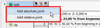 Choice of joint type
Members can be entered in a similar way. The window for input of new members is identical to "Member properties", the reference joints, cross-section and material have to be specified there.