Stiff end plate to column
Bending resistance
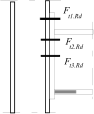
The bending resistance of the joint is calculated as the minimum of component resistances in the joint part in tension, that is limited by the resistance of components in compressive part of the joint. The plastic stress distribution is considered in the most of cases, sometimes, the elastic distribution is used. The procedure depends on the certain joint type. Elastic distribution is based on the most stressed bolt under the top flange, sometimes it is considered as an elastic distribution along the whole height of the cross-section made of bolts and part in compression.
The shear forces are distributed uniformly for elastic distribution. In plastic distribution, the shear forces are assigned only to bolts, that do not transfer the bending, or the shear and bending resistances are calculated with the help of interaction diagram. Tensile force has to contain the impact of prying. The slip resistance of preloaded bolts is not affected by the tensile forces in bolts, as the friction is considered only in the compressive part.
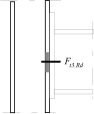
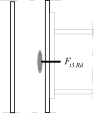
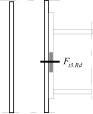
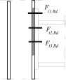
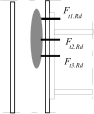
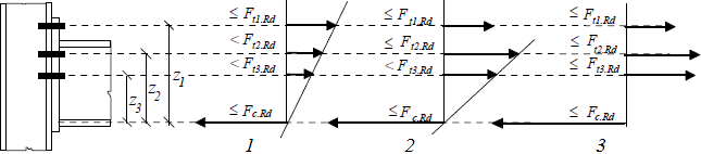 Stress distribution: elastic (1), elastic-plastic (2) and plastic model (3), resistance of i-row in tension Ft,i,Rd, the minimum resistance of components in compression Fc,Rd
The bending resistance of bolted connection for plastic distribution is calculated using expression
![]()
Where is: | Fti,Rd |
|
zr |
|
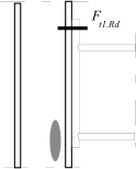
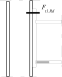
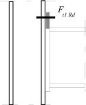
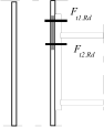
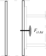
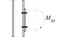
The axis of compressive part is considered in the axis of flange in compression. For one component in tension, the inner lever arm may be considered as the distance of axes of compressive and tensile components.
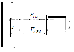 Inner lever arm for bolted joints with one row in tension
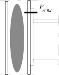
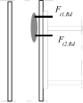
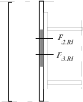
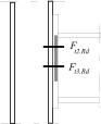
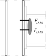
For more components (e.g. more rows of bolts) in tensile part, the equivalent stiffness of tensile part keq is used. This stiffness contains both the effect of particular components keff.i and the impact of arm of corresponding row on the stiffness of the tensile part.
![]()
![]()
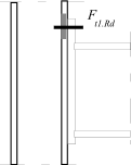
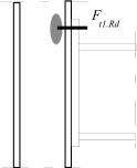
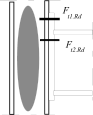
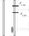
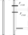
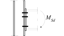
Inner lever arm for more rows of bolts may be calculated using approximate method according to the figura above or ma be calculated using following expression
![]()
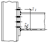 Inner lever arm
where zi is the distance of components in tension with stiffness keff,i from the centre of the part in compression.
The resistance of one row in tension Ft,Rd is calculated as a minimum of following values:
- The column flange in bending Ft,fc,Rd
- The column web in tension Ft,wc,Rd
- The end plate in bending Ft,ep,Rd
- The beam web in tension Ft,wb,Rd
The resulting resistance is limited by the resistance of part in compression and the resistance of web in shear:
- The column web in shear Vwp,Rd/β
- The column web in compression Fc,wc,Rd
- The beam flange in compression Fc,fb,Rd
The resistance of any row of bolts has to be reduced in case of more than one row of bolts in tensile part. The bearing capacity cannot be greater than:
- The column flange in bending Ft,fc,Rd
- The column web in tension Ft,wc,Rd
- The end plate in bending Ft,ep,Rd
- The beam web in tension Ft,wb,Rd
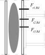
The effect of prying caused by the deformation of end plate has to be checked when designing the detail with end plate. The effect of prying is transferred into the analysis of equivalent T-stub. The increase of plate thickness avoid prying, as the decisive failure would be mode 3 in this case. This mode is not very suitable, as the resistance is given by the failure in bolts. In joints with full plastic hinges, the strengthening of material may affect the resistance of welds. The welds are designed using increased joint resistances in these cases. It means 1.4Mj,Rd for braced frames and 1.7Mj,Rd for unbraced frames. The effect of more rows is described in tables below:
The resistance of connection with three rows in tensile part: The resistance of first row Ft1,Rd is calculated first, next two rows are neglected
Column web in shear and compression, beam flange in compression |
|
|
|
Column web in shear Ft1,Rd≤ Vwp,Rd/β | Column web in compr. Ft1,Rd≤ Fc,wc,Rd | Beam flange in compr. Ft1,Rd≤ Fc,fb,Rd | |
Resistance of first row in tension |
|
|
|
Column flange in bending Ft1,Rd≤ Ft,fc,Rd | Column web in tension Ft1,Rd≤ Ft,wc,Rd | End plate in bending Ft1,Rd≤ Ft,ep,Rd |
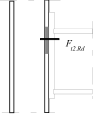
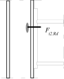
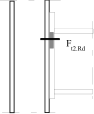
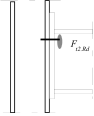
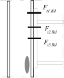
The resistance of second row Ft2,Rd follows, the third row is neglected
Column web in shear and compression, beam flange in compression |
|
|
|
Column web in shear Ft2,Rd≤ Vwp,Rd/β - Ft1,Rd | Column web in compr. Ft2,Rd≤ Fc,wc,Rd - Ft1,Rd | Beam flange in compr. Ft2,Rd≤ Fc,fb,Rd - Ft1,Rd | |
Resistance of second row in tension |
|
|
|
Column flange in bending Ft2,Rd≤ Ft2,fc,Rd | Column web in tension Ft2,Rd≤ Ft2,wc,Rd | End plate in bending Ft2,Rd≤ Ft2,ep,Rd | |
Resistance of second row in tension |
|
|
|
Resistance of two rows in tension | Beam web in tension Ft2,Rd≤ Ft2,wb,Rd | Column flange in bending Ft2,Rd≤ Ft(1+2),fc,Rd - Ft1,Rd | Column web in tension Ft2,Rd≤ Ft(1+2),wc,Rd - Ft1,Rd |
The resistance of third row Ft3.Rd follows
Column web in shear and compression, beam flange in compression |
|
|
|
Column web in shear Ft3,Rd ≤ Vwp,Rd/β - Ft1,Rd - Ft2,Rd | Column web in compr. Ft3,Rd ≤ Fc,wc,Rd - Ft1,Rd - Ft2,Rd | Beam flange in compr. Ft3,Rd ≤ Fc,fb,Rd - Ft1,Rd - Ft2,Rd | |
Resistance of third row in tension |
|
|
|
Column flange in bending Ft3,Rd ≤ Ft3,fc,Rd | Column web in tension Ft3,Rd ≤ Ft3,wc,Rd | End plate in bending Ft3,Rd ≤ Ft3,ep,Rd | |
Resistance of third row in tension |
|
|
|
Resistance of second and third rows in tension | Beam web in tension Ft3,Rd≤ Ft3,wb,Rd | Column flange in bending Ft3,Rd ≤ Ft(2+3),fc,Rd - Ft2,Rd | End plate in bending Ft3,Rd≤ Ft(2+3),wc,Rd - Ft2,Rd |
Resistance of second and third rows in tension |
|
|
|
Resistance of three rows in tension | Beam web in tension Ft3,Rd≤ Ft(2+3),wb,Rd - Ft2,Rd | Column flange in bending Ft3,Rd≤ Ft(1+2+3),fc,Rd - Ft1,Rd - Ft2,Rd | Column web in tension Ft3,Rd≤ Ft(1+2+3),wc,Rd -F t1,Rd - Ft2,Rd |
The impact of interaction between axial force and bending moment on resistance and stiffness is neglected up to the value 0.1 of beam resistance in compression (0.1Npl.Rd). The interaction diagram should be done for greater forces and the reduction similar to the column bases is necessary.
Bending stiffness
The tangential stiffness shows the dependency of bending moment on connection rotation
![]()
The initial stiffness Sj,ini is calculated using a sum of deformations of particular components. The tangential stiffness Sj is calculated for individual values of bending moments on non-linear part of moment-deformation diagram. The elastic deformation is calculated using formula
![]()
Where is | Fi |
|
E |
|
The rotation is calculated using following formula for the force Fi with inner lever arm z
![]()
The initial value of stiffness is calculated using expression:
![]()
The expression can be modified for non-linear part of the curve with the help of factor μ. The factor describes the difference between initial and tangential stiffness. The value of the factor is 1.0 in the linear part and is increasing with increasing value of bending moment.
![]()
Where is: | z |
|
ψ |
| |
κ |
| |
Med |
|
Components for calculation of stiffness:
| One row in tension: k1, k2, k3, k4, k5, k10 |
| Two and more rows in tension: k1, k2, keq (k3, k4, k5, k10) |
| One row in tension: k1, k2, k3, k4, k5, k10 |
| Two and more rows in tension: k1, k2, keq (k3, k4, k5, k10) |
| One row in tension: k2, k3, k4, k5, k10 |
| Two and more rows in tension: k2, keq (k3, k4, k5, k10) |
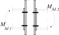
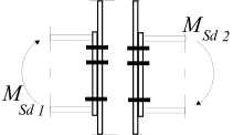
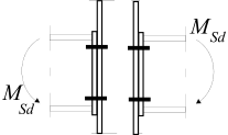
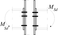
Note: Marking corresponds to EN 1993-1-8.
Where is: | k1 |
|
k2 |
| |
k3 |
| |
k4 |
| |
k5 |
| |
k6 |
| |
k7 |
| |
k8 |
| |
k9 |
| |
k10 |
|