Topology
The structure can be created in the program Fin 3D using these three ways:
- Direct input of the structure - The fundamental input of topology and loading. The topology is defined by the particular joints and members. Loads are organized into load cases and load combinations, it is possible to enter joint load or member load.
- Generator of 2D structures - The most common structures (trusses, attic roofs, frames) can be created easily with the help of the "Generator of 2D structures". This generator is able to create both the structure topology and the fundamental load. This tool is described in the chapter "Generator of 2D structures".
- Import from *.dxf file - The structure topology may be also imported from *.dxf in the window "Import dxf". This option is available in the main menu, part "File", "Import".
All these options may be combined (the basic part of the structure can be created in generator or imported from *.dxf, the second part of the work can be done with the available tools).
Input and editing methods
The methods of input and editing are described in chapters
The program in the mode "Tools" of the tree menu contains additional tools for the manipulation with elements and structures (move, copy, rotate etc.).
Types of elements
The structures consist of two basic types of structural elements: joints and members.
Two different types of joints are included: "absolute" and "relative". Special type of relative joint is the "scissor joint", that can be specified in the intersection of two members.
Absolute joints are the joints, that have the position specified by the coordinates [X,Y,Z] in the global coordinate system. Their position can be changed only by editing the coordinates. Absolute joints are usually used for input of fundamental shape of the structure. These joints are marked with cross in the workspace.
Relative joints have the position specified relatively to the reference member. The position on member is given by the distance from the beginning or end joint of the member. The distance may be specified in length unit (metres) or in a proportional unit. The joints may be placed between beginning and end joints of the member or may lie outside this segment and extend the member length. The position has to be specified by a negative value in this case. The relative joints are used for connections of members to the point placed on the other member (typically connection of webs to chords).
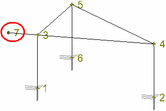 A cantilever created by the relative joint 7 that is placed in front of the reference joint 3
The position of the relative joint can be changed only in the direction of the local axis of the reference member. Relative joints are usually used in trusses for connections of webs to chords. These joints are marked with square in the workspace.
The differences between absolute and relative joints are also described in the chapter "Conversion of relative joint to absolute".
Scissor joint is a special type of relative joint, as it has two reference members. The position of such joint is given by the intersection of these reference members. This joint creates hinged connection of intersecting members.
Member is specified by start and end joints, cross-section, material and end conditions. The material and cross-sectional characteristics can be specified with the help of pre-defined databases, user input or by the import from programs "Section" and "Sector".
The member is connected to the reference joints by a connection, that consists of six components (three shifts and three rotations). Any of these components may be defined as free or spring.
Any member contains local coordinate system, that is used for the input of relative joints and load. The origin of this local coordinate system is the beginning of the member, local axis 1 is given by the member direction.
Member type
Program uses two basic member types: "Beam" and "Beam on elastic subsoil". The "Beam" is the fundamental member type locally supported in joints, "Beam on elastic subsoil" is the member, that is supported along the whole length by a subsoil (e.g. foundations).
Members are also described in the theoretical chapter "Structural elements".