FIN EC software

Online Help

Tree
Settings
Program:
Language:

Drawing settings

The window "Drawing settings" contains the settings that affect the display of the structure in the workspace. The window contains two tabs in the upper part: "Structure topology and loading" and "Results" (post-processor only). The bottom part contains settings, which affects both display of structure and results:

Load, internal forces and deformation only on selected members

  • Displays loads, internal forces and deformations only for selected members (highlighted by green in the workspace).

Show units for load, internal force and deformation values

  • The values of loads, forces and deformations are displayed including corresponding units

Correction of display size for load, forces and schematic deformations

  • Modifies the size of displayed diagrams. This setting is suitable for cases, when the default view doesn't provide readable results.

Text size

  • Modifies the font size in the workspace

Size of support symbols

  • Modifies the size of support marks and symbols of end conditions for members in the workspace

Structure topology and loading

Part "Common" contains following parameters:

Global coordinate system

  • Shows the axes of the coordinate system in it's origin

User coordinate systems

  • Shows the axes of the coordinate system in it's origin

Draw grid

  • Shows the snapping grid for the input of members and joints. The properties of the grid are located in the window "Options".

Next group of settings relates to joints and members:

Numbering

  • Shows the numbers of joints

Symbols

  • Shows the symbols of joints, that differentiate the absolute and relative joints

Supports

  • Shows the support marks

Numbering

  • Shows the numbers of members

Local axes

  • Shows the local coordinate systems of members. The orientation of local axes is important for the input of load.

End conditions

  • Shows the style of connections to the start and end joints of members. There are dedicated symbols for pinned and special (e.g. spring) connections. The fixed connection isn't highlighted by any symbol.

Beginnings

  • The beginning of the member is highlighted by the arrow. This information is helpful for the input of entities like relative joints or loads.

Sections

  • Shows the cross-sections of members

Equalize cross-sections (Fin 2D only)

  • Equalizes the size of displayed cross-sections. This setting is helpful in structures with significant differences in cross-sections dimensions (e.g. combination of thin steel and massive concrete cross-sections), as some cross-sections wouldn't be recognizable.

Scale (Fin 2D only)

  • This value is used as a size multiple for displayed cross-sections.

Last part affects the display of loads:

Draw joint load

  • Shows joint loads

Draw member load

  • Shows member loads

Equalize force load

  • The loads can be equalized using this setting. This is helpful in structures with significant differences in load values, as some loads wouldn't be recognizable.

Hatching of loads

  • This setting fills the displayed load with vertical hatching including orientation arrows.

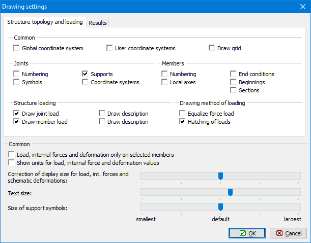
Window "Drawing settings"

Try FIN EC software yourself. Download Free Demoversion.