Deflection
This part of the beam design shows results of deflection verification (serviceability limit state) along the member length. The verification is performed only for load combinations that are dedicated to the serviceability limit state design. If there isn't any load combination for serviceability limit state, the results aren't available. The frame in the bottom part contains these settings for deflection verification:
Quasi-permanent combinations
Limiting value for deflection caused by the combinations with specified type "Quasi-permanent (SLS)" can be specified in this part. Deflection control for quasi-permanent combinations is defined in the chapter 7.4.1 of EN 1992-1-1. These options are available:
l/250 - Common requirements |
|
l/500 - Strict requirements |
|
l/ - User defined requirements |
|
Deflection |
|
Characteristic (Frequent) combinations - user defined requirements
Requirements for deflection caused by characteristic and frequent combinations aren't specified in the design standard. User defined limits for such deformations can be defined in these parts. The limits can be entered as span depending or absolute values.
Shrinkage and creep
This part contains basic inputs for the calculation of creep coefficient. The start and end of drying shrinkage can be specified here. More inputs and detailed results can be shown in the window "Creep" that can be launched by the button "Creep coefficient".
Complete results can be displayed in a new window after using the button "In detail". The workspace is able to show diagrams of bending moments and deformations (maximum and minimum values, particular components). Displayed quantities can be switched on/off in the window "Drawing settings", that can be launched using the button "Diagrams". The results for envelope of all relevant load combinations are displayed as a default. Results for certain load combination can be displayed with the help of drop-down menu in the heading of input frame. Some quantities (particular components of deflection) cannot be displayed for envelope of load combinations.
Calculation and verification of stress are described in the chapter "Serviceability limit state" of the theoretical help.
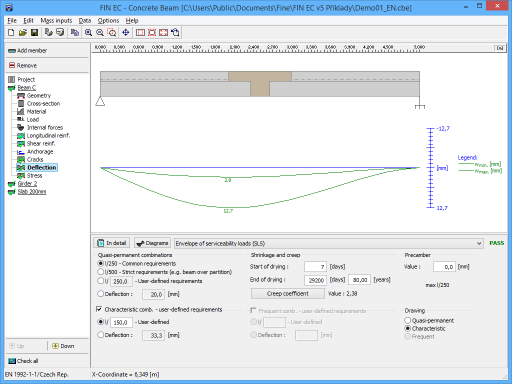 Part "Deflection" of member design