Analysis
This part contains tools for the input of shear reinforcement and also displays results of the analysis.
Calculation parameters
The bottom part contains an option to specify the input method of the coefficient β. Following options are available:
Consider β according to 6.4.3(6) |
|
Calculate β according to 6.4.3(3-5) - in moment direction |
|
Calculate β according to 6.4.3(3-5) - in axes directions |
|
User defined value β |
|
Always consider reinforcement in the range 0 to 2d |
|
The setting "Maximum resistance of reinforced perimeter" affects the value of the factor kmax. This factor is a ratio of maximum resistance of reinforced perimeter and a slab resistance.
Consider kmax according to 6.4.5(1) |
|
Consider kmax for double headed studs |
|
User defined value kmax |
|
The procedures used during the analysis are described in the chapter "Punching" of the theoretical help.
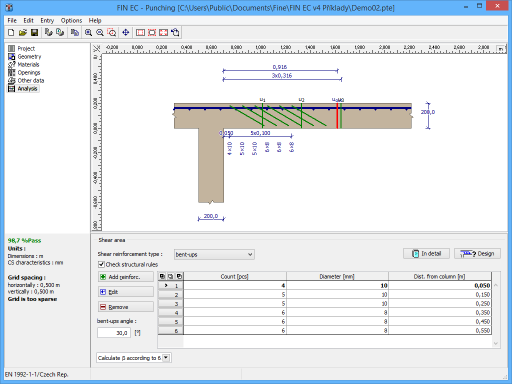
Reinforcement input
Three different types of shear reinforcement are available for the input:
- radial stirrups - the shear reinforcement is organized in radial rows (figure 6.22A in EN 1992-1-1)
- concentrated stirrups - - the shear reinforcement is organized in concentric rows
- bent-ups - shear reinforcement made of bent-up bars
The structural rules are also checked during the analysis. This control may be switched off with the help of the setting "Check structural rules". The structural rules are described in the theoretical part of help in the chapter "Punching - structural rules".
Two basic ways may be used for the input of the reinforcement: automatic design and manual input. The automatic design may be run by the button "Design". Parameters of the automatic design has to be specified in the window "Reinforcement generation", that appears after clicking on the button. The manual input of individual rows of the reinforcement can be done with the help of tools in the input frame. The parameters differ according to the reinforcement type. The diameter, spacing, position of the first link leg and number of branches has to be specified for radial stirrups. The reinforcement for other types is organized in the table, every row means one perimeter of the reinforcement. The number of bars per one perimeter means number of link legs in all cases. it means that number of double-sided bent-up bars for real structure is the half of the number specified for the design. The reinforcement in the table may be added and modified with the help of the toolbar on the left side of the table. Reinforcement properties are organized in the window "Reinforcement edit".
Analysis
Results of the analysis are displayed in the left part of the main window. Detailed results may be displayed using button "In detail". These results are displayed in the new window, text in this window can be copied into clipboard using shortcut Ctrl+C and pasted into a document. Following three situation may be the result of the analysis:
Reinforcement not possible |
|
Fail |
|
Pass |
|
 Part "Analysis"