Edit member node
Properties of node (support) can be defined in this window. Basic parameter is the position of the node (marked as "X-coordinate" in the window) that is measured from the beginning of the member. These node types are supported:
Calculation node | |
Hinged | - Support fixed in vertical direction, free in rotation
|
Fixed | - Support fixed both in vertical direction and in rotation
|
User support | - Support with possibility to define the stiffness both in vertical direction and in rotation
|
Middle hinge | - Middle hinge in a beam bay. Only shear forces are transported in this point, bending moment is equal to 0.
|
Next input is the "Support width" that is used for example for the reduction of bending moments in the part "Longitudinal reinforcement".
General support
This part contains parameters for the calculation of support stiffness for node type "User defined support". These values should be entered when the setting "Enter A/L, I/L" is switched on:
A/L | - Ratio of total cross-sectional area of vertical structural members supporting the beam (A) and their length (L). Typical examples of such structural members are columns. This ratio is used for the calculation of support stiffness in the vertical direction. The assumption is that the supporting members are made of concrete. For any other material, recalculation of area to equivalent area for concrete material is necessary. The ratio of moduli of elasticity should be used in these cases.
|
I/L | - Ratio of total moment of inertia of vertical structural members supporting the beam (I) and their length (L). Typical examples of such structural members are columns. This ratio is used for the calculation of rotational support stiffness. The assumption is that the supporting members are made of concrete. For any other material, recalculation of area to equivalent area for concrete material is necessary. The ratio of moduli of elasticity should be used in these cases.
|
In other cases, these values are automatically calculated using following inputs:
Width b | - Width of cross-section of supporting members (columns). The cross-sectional dimension perpendicular to the beam direction should be used for this input.
|
Height h | - Height (Depth) of cross-section of supporting members (columns). The cross-sectional dimension in the beam direction should be used for this input.
|
Length L | - Length (height) of structural members (columns) that support the beam
|
These values are used for calculation of A/L and I/L ratios. The area and moment of inertia are multiplied by two for setting "Member from both sides" as the connections from both (bottom and upper) sides are considered.
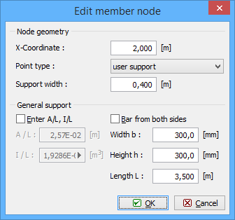 Window "Edit member node"