Fire resistance of RC column
Introduction
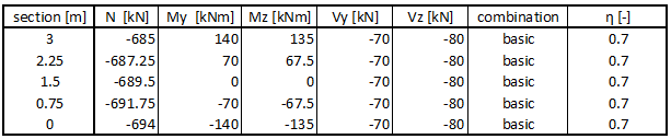
This tutorial shows a design of reinforced concrete (RC) column subjected to fire. The column has rectangular cross-section with dimensions 400x300 mm and length 3000 mm. The column is subjected to axial compressive force, biaxial bending and lateral forces from both directions. The internal forces in the Ultimate Limit State (ULS) are shown in the table below and were calculated based on the basic combination. The column is located inside of an office building and is considered to be rigid at the bottom and hinged at the top. The material of the column is concrete C35/45 and steel reinforcement B550B.
 The internal forces in the column
Starting a new project
The following screen appears after running the software "Concrete Fire":
 The start window of the software "Concrete Fire"
The software allows to asses unlimited number of tasks per one project. The supported tasks are, the assessment of cross section ("Section") or the whole member ("Member"). The "Section" may be used for simple verification of RC cross-sections subjected to fire, where the "Member" is usually used for the design of structures created in "Fin 2D" and "Fin 3D". This example shows the use of "Section" analysis. The start screen contains a part "General project data", where the job name, description and other project identification data can be entered. After clicking the "Edit" button, we first enter the job name and other project details:
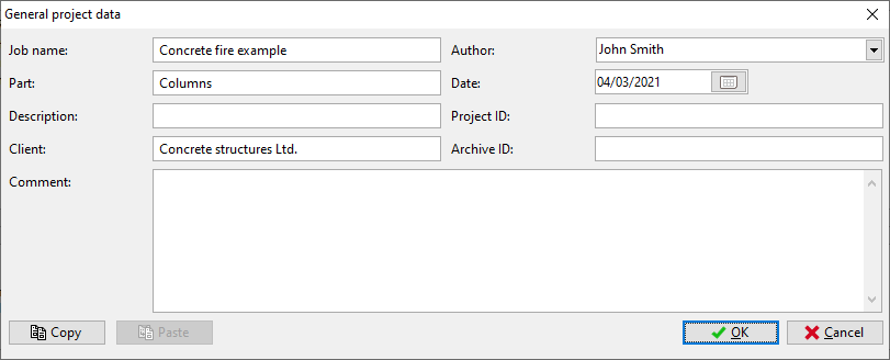 "General project data" dialog box
These data is displayed in the header or footer of the final documentation. Next, click the "Edit" button in the "Standard" frame and select the appropriate national annex. The supported national annexes are listed in the drop-down list. In case, the proper national annex is not listed, it is possible to choose User defined and set up custom coefficients.
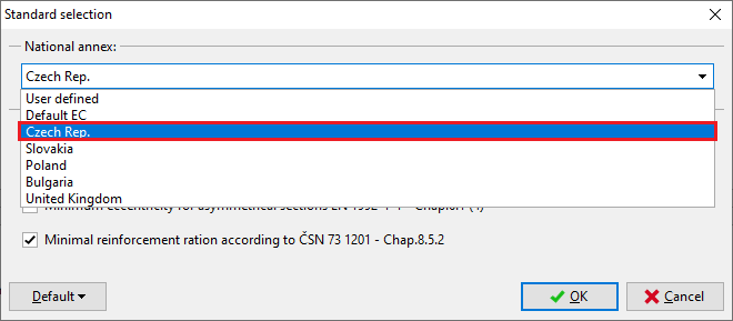 Selection of the standards
Last, the fire resistance properties are set in the "Fire resistance parameters" part. This project data can be edited any time during the analysis.
Before any data is assigned to the project, it is highly recommended to save the file. This can be done either using "![]() " button, or in the main menu clicking on "File" – "Save As", or using the "Ctrl+S" shortcut.
" button, or in the main menu clicking on "File" – "Save As", or using the "Ctrl+S" shortcut.
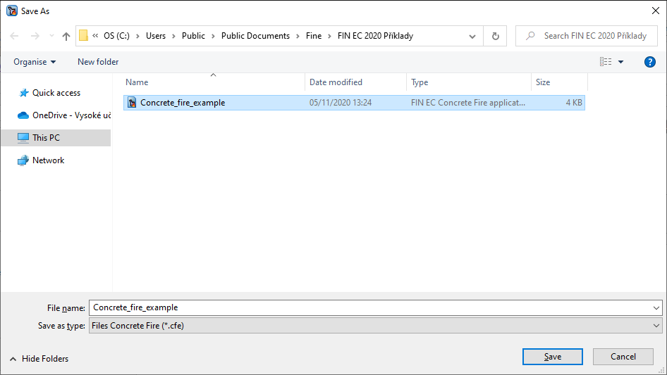 Saving the project
Now we can proceed to entering a new task by clicking the "Add Section" button in the upper part of the program’s tree menu.
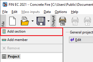 Adding a new section
The following dialog box appears, in which we can enter the section’s name ("Column") into the "Section description" field, confirming by clicking the "OK" button.
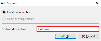 Dialog box for adding a new section
The new task "Column C1" has been created in the tree menu, every time a new "Section" or "Member" is created, it will appear in the tree menu. The software has automatically selected the "Column C1", therefore it is possible to directly edit this task. In the right bottom corner it shows what is required in order to run the analysis.
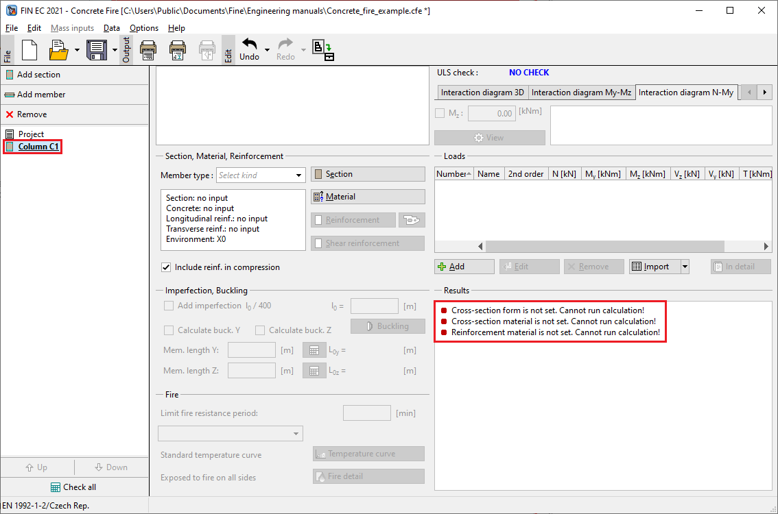 Main screen for "Section" task type
Section, Material, Reinforcement
In the beginning it is necessary to enter the dimensions of the geometrical and material characteristics of the considered RC column in the "Section, Material, Reinforcement" frame. First select the type of the member in "Member type" drop-down list. Available types are "beam", "slab", "column" or "wall".
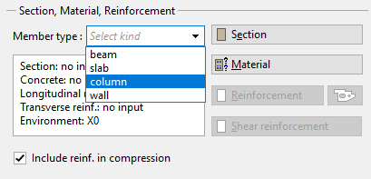 Defining the member type
In our example we select member type "column". This selection affects the analysis and verifications of the reinforcement arrangement.
By clicking the "Section" button, the cross-section can be defined by the first suggested rectangular shape. The dimensions of the cross-section are simply defined by changing it's height and depth. The software allows to use custom user-defined shapes, however for the purpose of this example it is not needed.
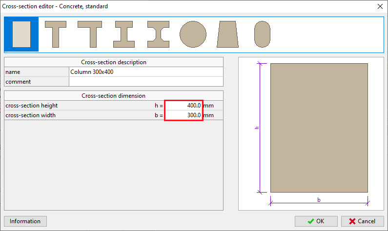 Geometry of the column
We proceed with defining the material properties in "Materials" dialog box which is run by clicking the "Material" button in the "Section, Materials, Reinforcement" part. Assuming the column is located inside of the structure we select "X1" for "Exposure class", as the column is not in contact with outside environment. Subsequently we define the material properties of concrete and longitudinal and transversal reinforcement. We can select standardized materials from the library of pre-defined materials by clicking the "Catalogue" button at relevant lines.
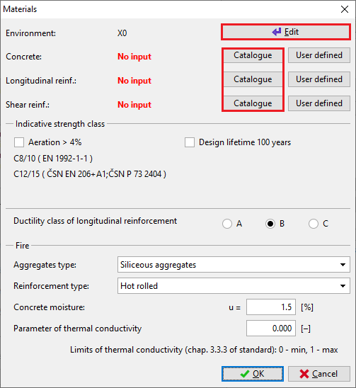 Window "Materials"
For column environment select the corrosion induced by carbonation "XC1" and close the dialog box by clicking "OK".
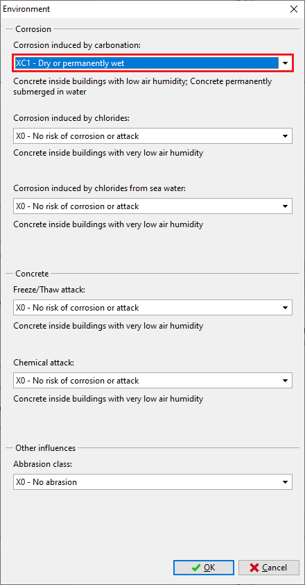 Selection of the column environment
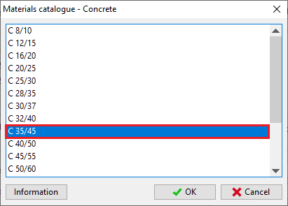
For concrete select the strength class "C35/45" and close the dialog box by clicking "OK".
 The strength classes of the concrete
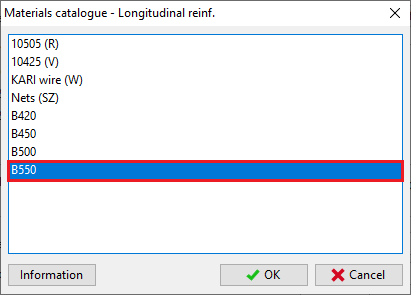
Proceeding to definition of the steel properties, select the grade "B550" for both longitudinal and transversal reinforcement and close the dialog box by clicking "OK".
 The steel grade classes
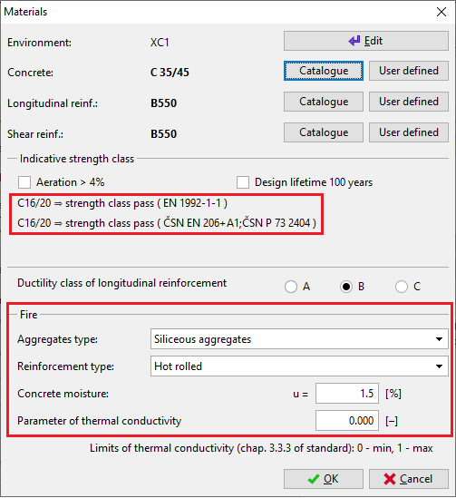
When returning to the "Materials" dialog box, the selected materials are checked with the predefined standard and displayed whether the material requirements on the "Indicative strength class" are fulfilled. At the bottom of the "Materials" dialog box, the material properties influencing the fire resistance properties can be changed. Finally, exit the window by clicking "OK".
 Indicative strength class check in "Materials" window
Loads
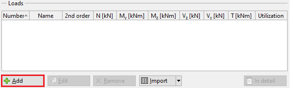
After defining the geometry of the section and material properties, either the loads or the reinforcement may be defined. In this example, the load is defined first, then the reinforcement can be assessed immediately during its definition. The load case is created by clicking the "Add" button located under the "Loads" table.
 Inserting the new load
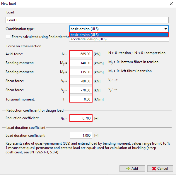
In the "New load" window select a "Combination type". This type should be selected according to the type of combination, which was used for determination of the forces and moments. This input affects the type of verification. The following options are available:
Basic design (ULS) |
|
Accidental design (ULS) |
|
In this example, the internal forces were calculated based on basic design combination, therefore pick the "Basic design (ULS)". Now in the dialog window add the internal forces on section 3m according to the table in the introduction. The axial force is N= -685kN (negative value denotes compression), the bending moments are My= 140Nm, Mz= 135kNm and the lateral forces are Vz= -80kN and Vy= -70kN (negative value denotes they act in the same direction as the moments). Next, define "Reduction coefficient", the procedure to determine this coefficient is in the chapter 2.4.2 of the standard EN 1992-1-2. As a simplification, the standard suggests to use ηfi with value of 0,7.
The "Load duration coefficient", i.e. the ratio of quasi-permanent and total loads for calculation of the creep coefficient. If the exact value is not available, the conservative value is 1.00, which means that the total load is considered quasi-permanent in the calculations. The new load is confirmed by clicking the "Add" button and "Cancel" to exit the dialog box.
 Defining the loads
As a result, the table summarizing all defined load cases is generated in the dialog box.
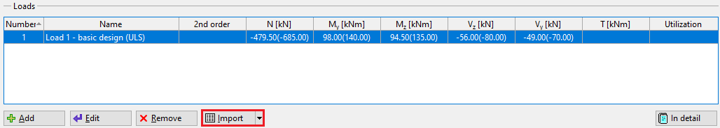 Overview of the loads
However, adding all the load cases one by one is quite time consuming, therefore the load cases can be imported in a batch using *.txt, *.xslx, *.csv file (button "Import"). The number of loads is not limited in the software.
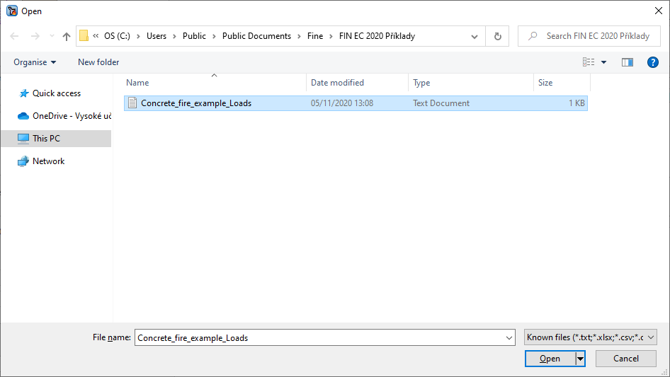 Load the *.txt file table data
The dialog box "Import of table data" will appear after loading the source file. In this dialog box it is possible to align the data from the source file to the group of data, that are recognized by the software. When the data is formatted in the same manner as in the table in the introduction chapter, the dialog box "Import of table data" will look similar as the picture below. Next, it is necessary to align the columns in the source file (4) with the columns of the imported data (5). Check the imported data in the result of import preview (6) and make sure the imported data are aligned with the source file.
 Import the data from the file
When clicking the button "OK" the load cases will appear in the dialog box "Loads". If the import of the load cases was done correctly, the first imported load case should match with the load case defined manually.
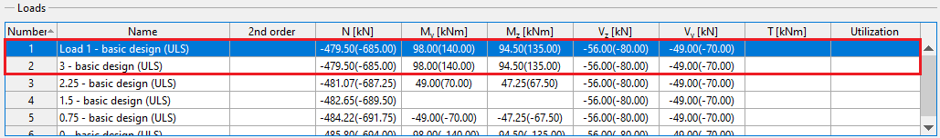 Overview of the loads with after the data import
Longitudinal reinforcement
When returning to the main dialog box, the longitudinal reinforcement is defined in the "Edit reinforcement" dialog that is accessed by the "Reinforcement" button in the "Section, Material, Reinforcement" frame. The upper part of the window allows to select calculation method for the cover. Keep the predefined method for now.
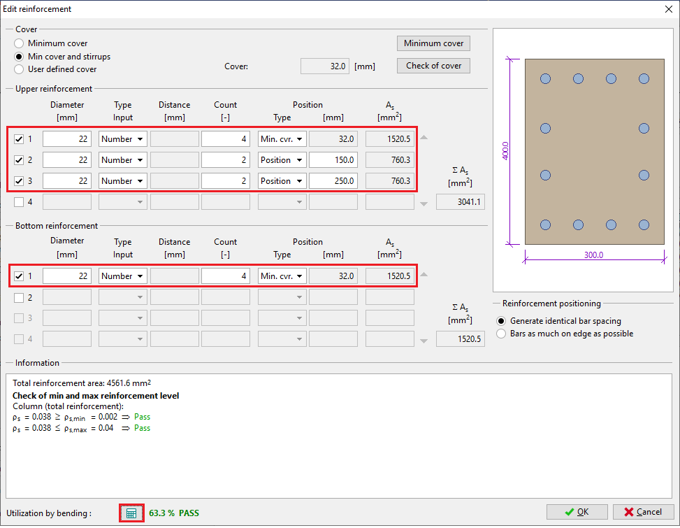 Defining the longitudinal reinforcement
When the reinforcement is defined, click "![]() " button and the software will check whether the cross-section has sufficient capacity in bending. It shows that the defined cross-section passes the design criteria with 63.3% utilization in bending. In the section "Information on reinforcement" it shows that the detailing requirements given by the code are satisfied. Next, check the minimum cover requirements by clicking the "Minimum cover" button:
" button and the software will check whether the cross-section has sufficient capacity in bending. It shows that the defined cross-section passes the design criteria with 63.3% utilization in bending. In the section "Information on reinforcement" it shows that the detailing requirements given by the code are satisfied. Next, check the minimum cover requirements by clicking the "Minimum cover" button:
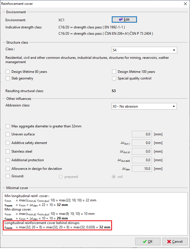 The minimal reinforcement cover
The minimum required cover may change, when the stirrups are defined. Therefore, you should always look into this dialog box, after the stirrups are defined.
Shear reinforcement
The shear reinforcement is defined by clicking the "Shear reinforcement" button. The column is subjected to lateral forces, therefore the calculation for the shear resistance must be made. Define the shear reinforcement and click "![]() " button, the software will check whether the cross-section has sufficient capacity in shear. It shows that the defined cross-section passes the design criteria with 49.3% utilization in shear.
" button, the software will check whether the cross-section has sufficient capacity in shear. It shows that the defined cross-section passes the design criteria with 49.3% utilization in shear.
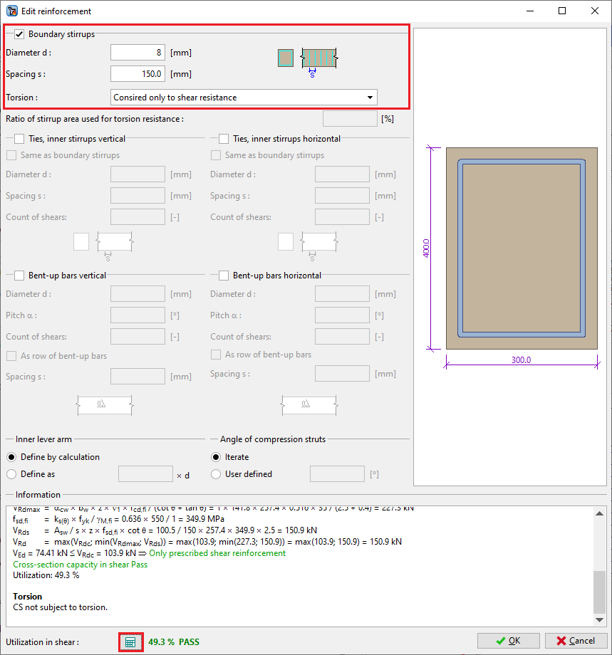 Defining the shear reinforcement
Buckling
The next step is defining the buckling parameters. First tick "Calculate buck. Y/Z" boxes followed by entering the nominal lengths of the column for both directions, based on which the effective buckling lengths will be calculated. For a column rigid at the bottom and simply supported at the top, the effective buckling length is reduced.
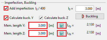 Defining buckling parameters
Define the boundary conditions by clicking the "![]() " buttons for each direction.
" buttons for each direction.
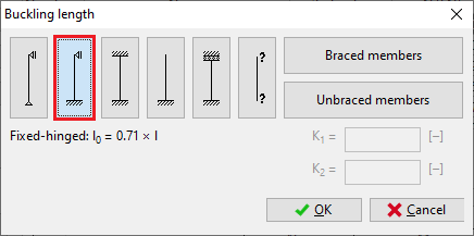 Setting the buckling length
Fire
Last, the parameters for the fire assessment are defined at the bottom of the main dialog box in the "Fire" frame. The software allows to do the calculations based on the "500°C isotherm method" or the "Zone method". For the column it is recommended to use the "Zone method".
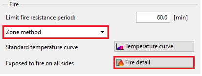 Fire calculation parameters
The picture of the temperature distribution is shown at the top of the main dialog box, under the "Temperature distribution" bookmark.
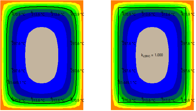 500°C isotherm method (left) and Zone method (right)
The position, where the fire is acting on the column is displayed in the "Fire detail button". The column is considered to stand alone, thus select the first fire detail.
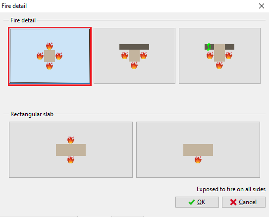 Fire detail
Results
When all the input has been defined, the results are shown in the main dialog box. If the defined element satisfies the software shows "PASS" at the top of the main dialog box.
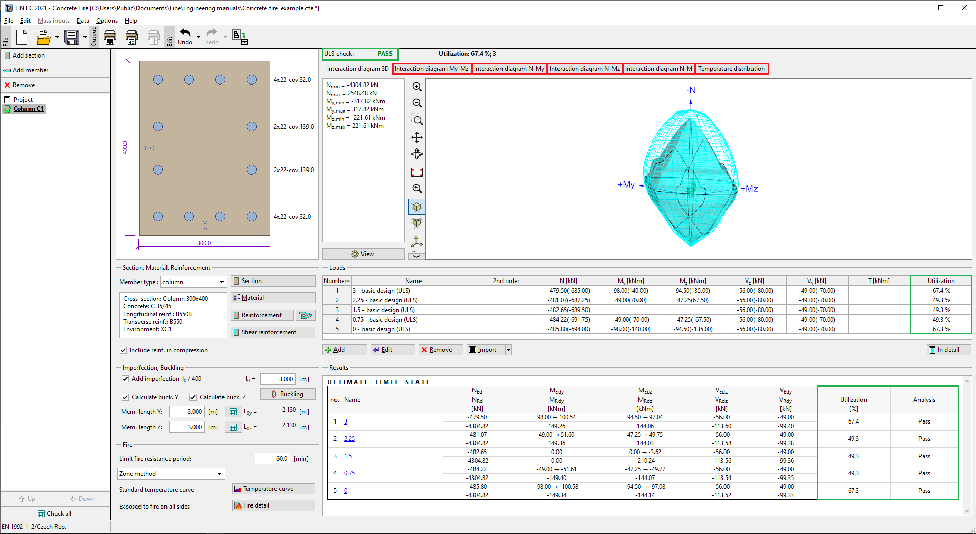 The main dialog box with the 3D representation of the interaction diagram
The results may be shown in terms of interaction diagram in the bookmarks at the top of the main dialogue box. The defined loads are shown as points in the interaction diagram. If the load lies inside of the solid line of the diagram, the cross-section satisfies the fire assessment. The dashed line shows the iteration diagram of the column without buckling.
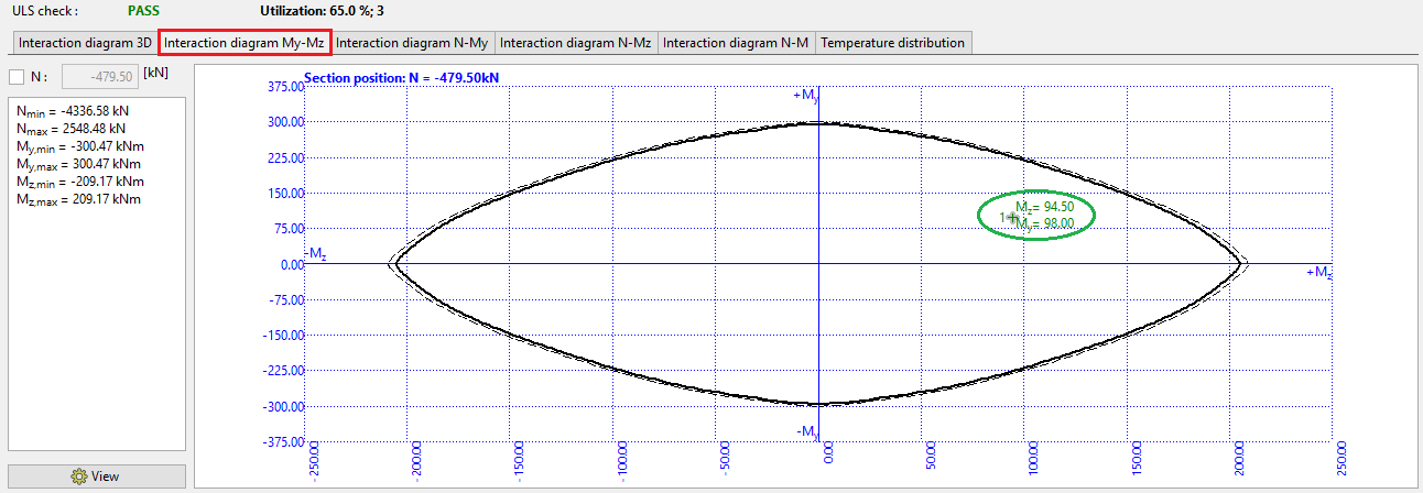 The My - Mz interaction diagram
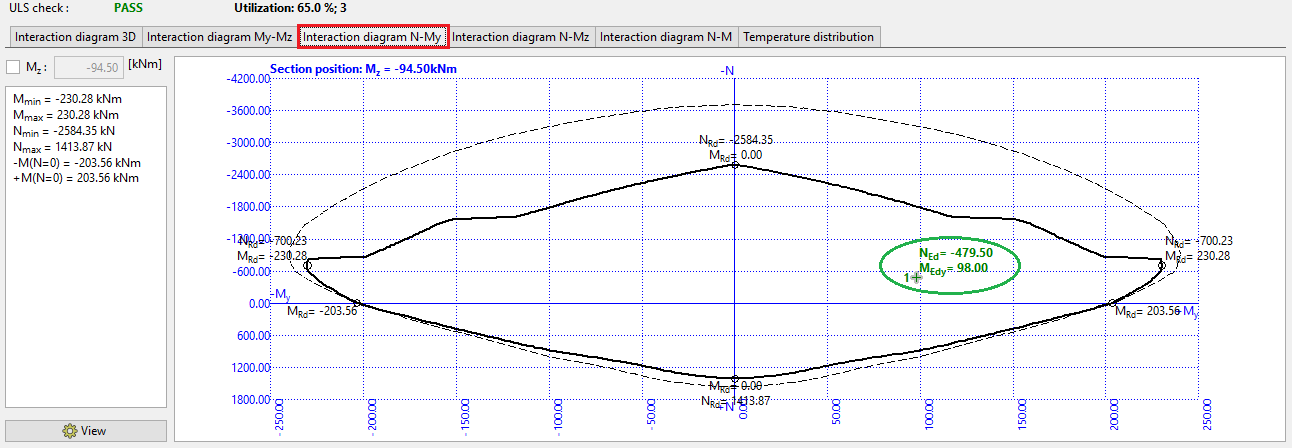 The N - My interaction diagram
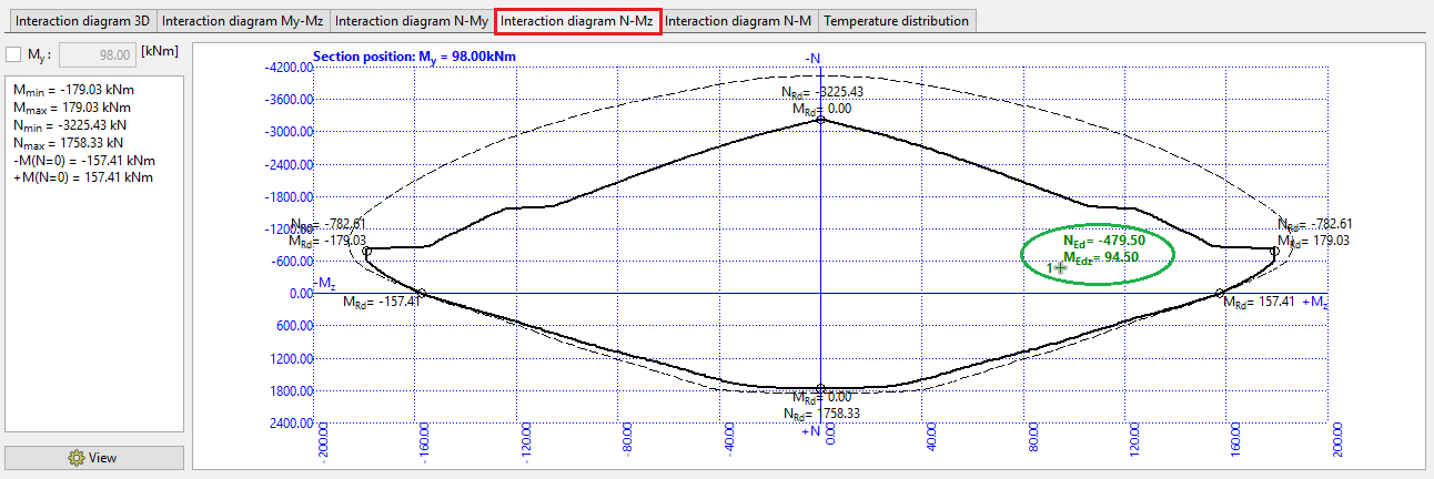 The N - Mz interaction diagram
When the project is finished, it is highly recommended to save the file by clicking "![]() " button, or in the main menu clicking on "File" – "Save As", or using the "Ctrl+S" shortcut. The indication of not saved state is "*" in the program window header. In such case it is advisable to save the state.
" button, or in the main menu clicking on "File" – "Save As", or using the "Ctrl+S" shortcut. The indication of not saved state is "*" in the program window header. In such case it is advisable to save the state.
 Indication of the not saved state
Outputs
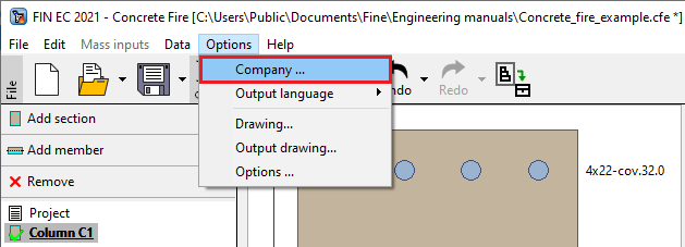
In order to show the information about the company in the output files, the information must be defined in the project. Click the button "Company" in the Options drop-down menu.
 Define the company information
The window "About the company" will appear, where the information about the company can be defined. It is also possible to import the company logo, that will show at the header of the exported documentation.
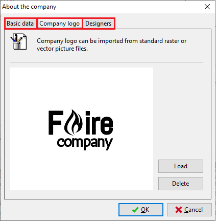 Set the company data and import the logo
If all the settings finished and saved, the output documentation can be composed. First print out a single title page summarizing all the input data and the check results. This is done by clicking the "File" and "Graphic output" or "![]() " in the toolbar.
" in the toolbar.
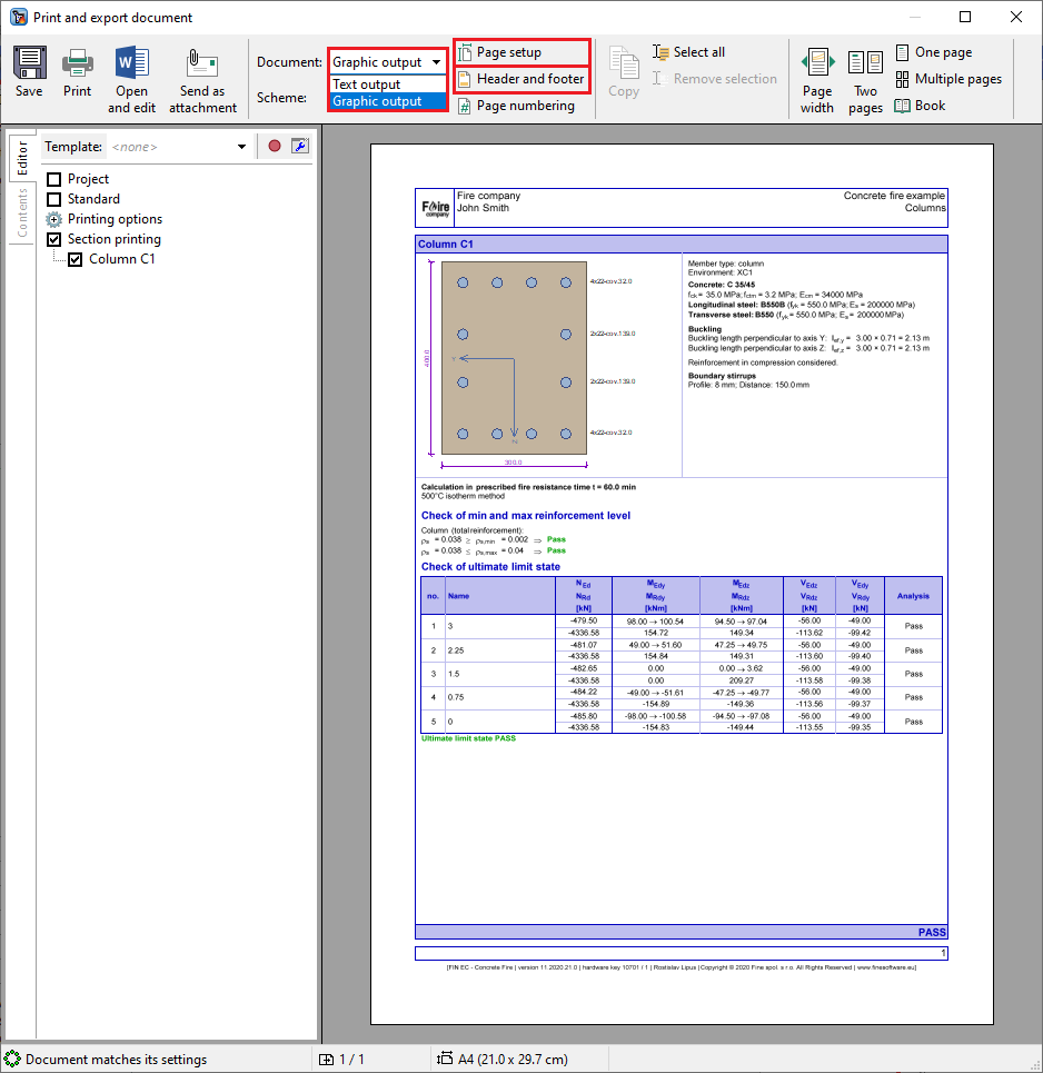 The graphic output
At the top part of this window, there are buttons "Page setup" and "Header and footer". Click the button "Page setup" and a window for editing the paper size, margins or a colour of the output document will appear. Pick the preferred colour based on your liking and continue.
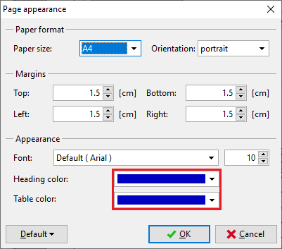 Page appearance settings
When clicking the button "Header and footer" the window for adding information about the project to the header or footer of the output documentation will appear. Check the "insert company logo" box in order to show the company logo in the header. The other information about the project can be also added to the footer or header by clicking the button "Insert".
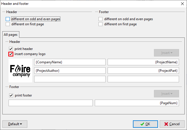 Header and footer settings
Apart from this title document, the detail text output can be composed by clicking the "![]() " button in the toolbar or selecting "File" and "Text output" in the main menu. If the print and export document dialog box is still opened, the document type can be changed in the toolbar’s "Document" drop-down list.
" button in the toolbar or selecting "File" and "Text output" in the main menu. If the print and export document dialog box is still opened, the document type can be changed in the toolbar’s "Document" drop-down list.
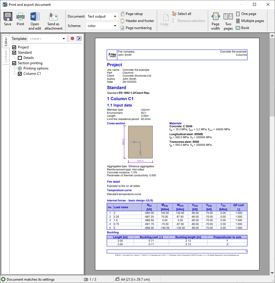 The text output
After switching to the "Text output" mode, the parts of the documentation can be added or excluded in the "Editor".
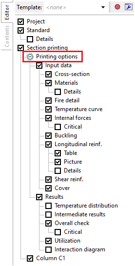 Add or exclude the output parts
The software will immediately re-generate the output to reflect each change made in the settings in the tree on the left-hand side. Once the output contains all required information, the document can be again saved on disk.
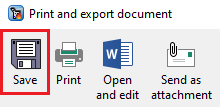 Click the save button
The document can be printed directly by clicking "![]() " button or save it on disk as *.pdf or *.rtf file by clicking "
" button or save it on disk as *.pdf or *.rtf file by clicking "![]() " button.
" button.
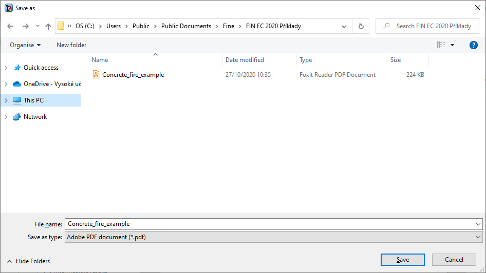 Saving file in *.pdf format
Completing the outputs generation, the work is done.