Section
Task type "Section" is suitable for the fast verification of the concrete cross-section, that is loaded by unlimited number of loads. General work with particular tasks of the project (addition, manipulation) is described in the chapter "Tree menu".
Section, Material, Reinforcement
This part contains the main characteristics of the cross-section that shall be specified first.
The fundamental parameter is the member type. The member type influences both the analysis and structural rules. Differences are described in the theoretical part of the help in the chapter "Member types".
The following characteristics are organized into the dedicated windows that may be launched by corresponding buttons. Some of them (mainly reinforcement) are disabled at the beginning. They require input of the previous parameters (geometry of the cross-section and material) as the launching mode of these windows depends on these characteristics.
Section |
|
Material |
|
Reinforcement |
|
General reinforcement |
|
Shear reinforcement |
|
Include reinforcement in compression |
|
Cross-section view is active, mouse click on the cross-section launches the window for cross-section edit.
Imperfection, Buckling
This part contains parameters of imperfection and buckling. The imperfection of l0/400 may be considered in accordance with the chapter 5.2(9) of EN 1992-1-1. The fundamental length l0 has to be specified for the imperfection. This fundamental length l0 is the real length of the member, not the buckling length. If the buckling analysis is switched on for certain direction, this value is automatically copied to the input fields for fundamental lengths for buckling analysis "Mem. length Y" and "Mem. length Z". These values may be rewritten without any change of the value l0. The pinned supporting style is considered as a default, the buckling length is equal to the fundamental length in this case. The different supporting style for directions Y and Z may be selected in the window "Buckling length" that is available after clicking on the button "![]() ". The button "Buckling" opens the window "Buckling" that contains complete buckling parameters including the analysis method, creep factor etc.
". The button "Buckling" opens the window "Buckling" that contains complete buckling parameters including the analysis method, creep factor etc.
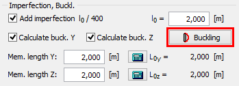 The button for opening the buckling properties
Fire
This part contains parameters related to the fire resistance analysis:
Limit fire resistance period |
|
Method |
|
Temperature curve |
|
Fire detail |
|
Interaction diagram
This part shows the bearing capacity of the cross-section as the 3D object in the chart with axes N, My and Mz (or in the planar chart with axes N and My for verification type "2D"). Verification of loads within the displayed area is OK, verification of loads located outside the displayed area fails. The program is also able to show the most significant sections:
- Interaction diagram My-Mz - the horizontal section of the 3D diagram. The section is created for given axial force, which can be specified in the right upper corner. If not specified, the axial force for the active load is used.
- Interaction diagrams N-My or N-Mz - the vertical sections of the 3D diagram. The sections are created for given bending moments Mz or My, which can be specified in the right upper corner. If not specified, the corresponding bending moment for the active load is used.
- Interaction diagram N-M - the vertical sections of the 3D diagram. This section is given by the point [0,0,0] and by the point which represents the active load.
The button "View" in the right bottom part of the diagram opens the window, which contains the options for displaying the diagram with or without the effect of buckling and for changing the appearance of the diagram. In sections, the dashed line shows the bearing capacity of the cross-section, thick line shows the bearing capacity including the buckling consideration.
The interaction diagram is active and may be used for the insertion of new loads. The click into the interaction diagram inserts new load with the combination of internal forces according to the coordinates of the click. Cursor position is also displayed in the status bar. Other forces in the inserted load (shear forces, torsional moment) are equal to 0.
The right button click in the interaction diagram opens a context menu that contains tool for exporting the coordinates of interaction diagram into *.csv file.
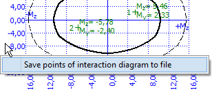 The context menu for interaction diagram
Temperature distribution
The thermal distribution in the cross-section may be displayed instead of interaction diagram with the help of the tab "Temperature distribution".
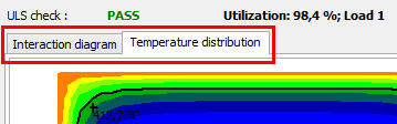 Tabs for switching the interaction diagram and temperature distribution
The temperature distribution for specified fire resistance is displayed with the help of isolines. Following settings may effect the drawing:
Draw effective section |
|
Draw reinforcement temperature |
|
Draw stirrups temperature |
|
The cursor is able to show the temperature for specified fire resistance in any point of the cross-section.
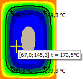 The displayed temperature in the point of cursor
Loads - internal forces
This part contains list of loads (combinations of internal forces and moments), that are checked during the verification. Loads can be added in the table using buttons "Add", "Modify" and "Remove". Table shows the most important information for each load (mainly internal forces and result of analysis). Load properties are entered with the help of window "Load edit".
Loads may be also imported from text or *.csv file. This feature is suitable for import of large number of loads that were calculated with the help of another structural engineering program. Import may be performed using the window "Load import" that may be launched by button "Import".
Results
The overview of results for all loads are displayed in the right bottom part of the main window. Detailed results for the active load in the loads table may be displayed using button "In detail". These results are displayed in the new window, text in this window may be copied into clipboard using shortcut Ctrl+C and pasted into a document.
Analysis is described in the theoretical part of the help.
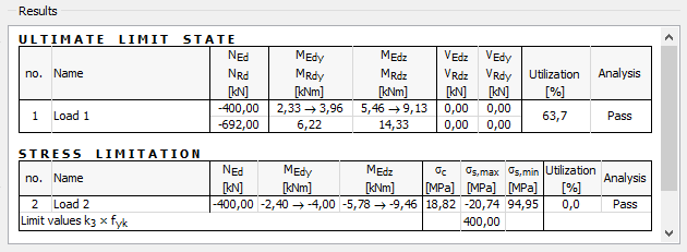 Part "Results" of the cross-section design