Base plate in bending
The behaviour of base plate and bolts is described with the help of the equivalent T-stub. The differences in the behaviour of base plate and end plate (Wald; 1993) were considered in the component method. The base plate is thick, as it is designed for the transfer of compressive forces into the concrete foundation. The bolts are longer, therefore, the stiffness is reduced. The impact of washers and nuts sizes is more significant. The impact on the overall stiffness may be neglected (Sokol, Wald; 1997).
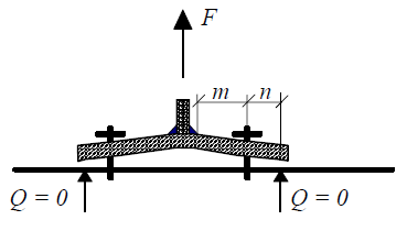 T-stub without any contact with concrete foundation
Simplified assumptions in accordance with (Weynand; 1999) are used for calculation of stiffness and resistance of bolts in tension and base plate in bending. The limiting value for the cases with prying and cases without any contact between plate and foundation is n= 1,25m.
![]()
Where is: | As |
|
Lb |
|
The effective length of concreted bolts Lb consists of the free part above the foundation surface Lbf and the effective part under the surface Lbe≈ 8d. It means Lb= Lbf+Lbe (Wald; 1993). The prying does not occur for bolts lengths Lb longer than Lb.lim.
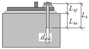 The effective length of bolt
The resistance of effective T-stub is the minimum of three plastic failures. The failure F1 corresponds to the failure of T-stub with thin base plate and long bolts. The mechanism with four plastic hinges appears in plate in this case.
The failure F3 corresponds to the thick plate with weak bolts. The failure appears in bolts in this case. The failure F2 is the intermediate case with two plastic hinges and failure in bolts.
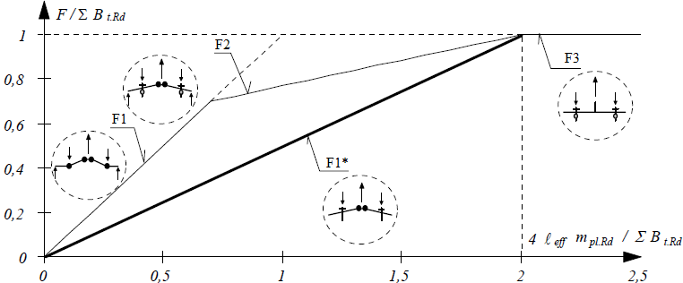 Failure modes (Bt.Rd is bolt resistance in tension and mpl.Rd is the plastic resistance moment)
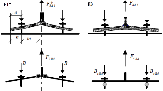 Failures F1* (no contact with concrete foundation) and F3 (bolts)
For cases without prying, the failure F1* appears instead of failure modes F1 or F2. As the contact between plate and foundation usually appears after the appearance of plastic hinges, the failure modes F1 or F2 appear. However, these modes are connected with significant deformations. Therefore, the failure mode with two hinges is checked. The resistance is given by the formula
![]()
The method of linear hinges is used for the calculation of the effective length of T-stub leff.1.
Stiffness
The stiffness factor of the equivalent T-stub without any contact with foundation is calculated separately for plate (thickness t) and bolts:
![]()
![]()
The stiffness of complete T-stub is calculated as a sum of these components. For cases with prying, following expressions are used in accordance with EN 1993-1-8:
![]()
![]()
The effective length leff of equivalent T-stub is equal to0 leff,1 or leff,2, according to the failure mode for ultimate limit state. leff is calculated using the method of linear hinges:
Base plates with bolts between flanges:
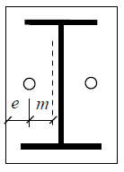 Bolts between flanges
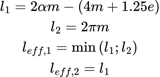
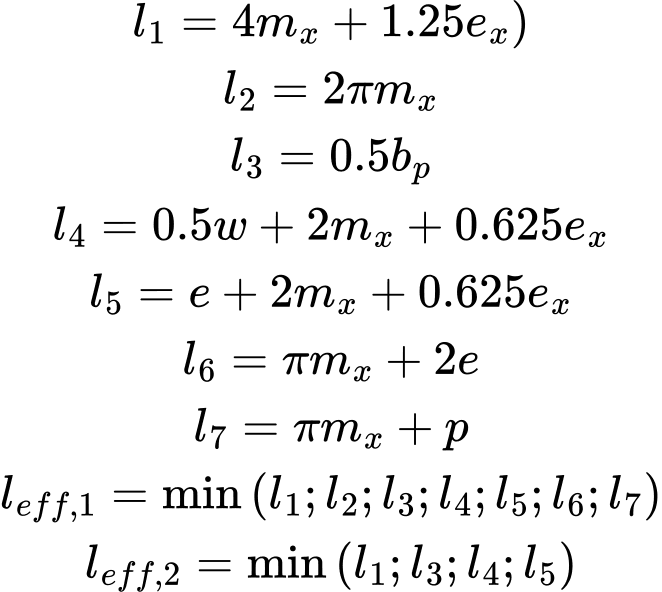
Values leff,1 and leff,2 are given by following expressions for cases with prying effect:
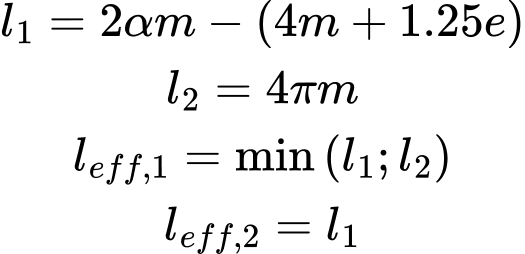
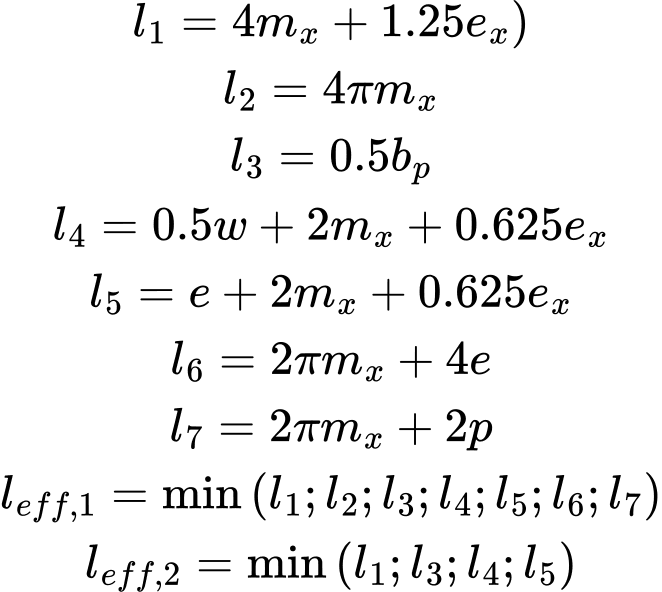
Values leff,1 and leff,2 are given by following expressions for cases without prying effect:
Base plates with bolts out of flanges:
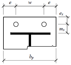 Bolts out of flanges:
Values leff,1 and leff,2 are given by following expressions for cases with prying effect:
Values leff,1 and leff,2 are given by following expressions for cases without prying effect:
References
Wald F., Obata M., Matsuura S., Goto Y.: Prying of Anchor Bolts, Nagoya University Report, Nagoya 1993, pp. 241-249.
Column Bases in Steel Building Frames, ed. K. Weynand, EC, Brussels 1999.
Sokol Z., Wald F.: Experiments with T-stubs in Tension and Compression, Research Report, CVUT, Praha 1997.