Resistance of base
The calculation of base resistance loaded by axial force and bending moment is based on the equilibrium of forces in base plate. The tensile resistance is given by the bolts resistance Ft.Rd. With the help of this value, the position of neutral axis and bending resistance MRd for axial force NEd may be found. The plastic distribution of stress is considered
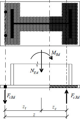 Equilibrium of inner forces
In case that only effective areas under flanges are considered (Steenhuis 1999) and only NEd, MEd are used, the solution is easier, as the axis of compressive part is equal to flange axis. This assumption may be used also for short cantilevers, that are shorter than the effective width of plate. The tensile force acts in the bolts axis, the resultant is used for two rows of bolts.
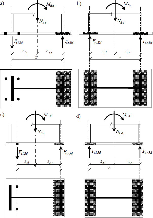 Equilibrium of forces for model with effective areas under column flanges; a) two bolts rows in tension, b) Two flanges in compression, c) one row and cantilever shorter than effective width, d) both flanges in compression and short cantilevers
The resistances in tension Ft,l,Rd and compression Fc,l,Rd, Fc,r,Rd were found in previous chapters. The expression e= MEd/NEd≥ zc.r is valid for cases with bolts in tension. According to the options a) and c), the base parts in tension and compression may be found using expressions:
![]()
![]()
The bending resistance of column MRd for given NEd may be calculated as the minimum of values MEd in expressions above.
![]()
If the eccentricity e= MEd /NEd < zc,r (options b) and d)), there is not any tensile force in bolts. Bending resistance is given by the following expression in these cases
![]()
References
Steenhuis C. M.: Assembling procedure for base plates, report 98-NOC-R0447 TNO, Delft 1999, p. 79.