Loads
This window contains options and settings for load input.
Load
The load name and combination type can be specified in this part. The combination type influences the analysis method. These types are available:
Basic design (ULS) |
|
Accidental design (ULS) |
|
Characteristic (SLS) |
|
Quasi-permanent (SLS) |
|
Frequent (SLS) |
|
If the check box "Forces calculated acc. to 2nd order theory", the analysis for this load will be performed without any consideration of buckling (the forces are already calculated on deformed structure.
Force on cross-section
This part contains input fields for internal forces. Following forces are supported:
N |
|
My |
|
Mz |
|
Vz |
|
Vy |
|
T |
|
The input range depends on program and task type.
Reduction coefficient for design load (only program "Concrete Fire")
Reduction coefficient for the design load ηfi recalculates the load determined for fundamental design combination into the design values for the fire situation. This coefficient should be obtained in accordance with 2.4.2 of EN 1992-1-2. As a simplification, value of ηfi= 0.7 may be used.
Load duration coefficient
This coefficient represents the portion of quasi-permanent component in the design load. Value 0 means that the load doesn't contain any quasi-permanent part, value 1.0 means that complete load is quasi-permanent. This coefficient is important for the calculation of the creep factor.
Proportion of reinforcement to concrete stiffness
This factor is available for design standard EN 1992-2, load types "Quasi-permanent" and "Characteristic". The value represents the ratio of stiffness of reinforcement and concrete. For standard conditions, this ratio is calculated with the help of moduli of elasticity. This solution doesn't respect the degradation of modulus of elasticity of concrete due to creep and similar effects.
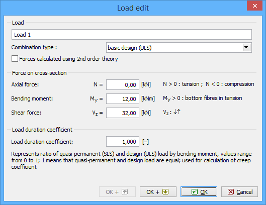 Window "Load edit"