Anchorage of column with end plate
Introduction
This guide shows how to calculate resistance of column connection to the concrete base using detail with end plate and haunches. The column is loaded by the axial force Nx= 500kN and bending moment My= 60kNm. The steel class EN 10025:Fe360 and concrete class C20/25 are used.
Column: | b= 150mm, h= 300mm, tw= 12mm, tf= 16mm |
Haunches: | tw= 16mm, hw= 90mm, Lw= 300mm, Lf= 50mm, aw= 6mm |
Concrete base: | bb= 1600mm, ab= 1600mm, hb= 1000mm, tg= 30mm |
Welds: | aw,f= 8mm; aw,w= 6mm |
End plate: | bp= 180mm, hp= 510mm, tp= 30mm, a1= -105mm |
Bolts: | M24 10.9, w1= 45mm, e= [50,410]mm |
Starting a new task
We use a project created in previous tutorials.
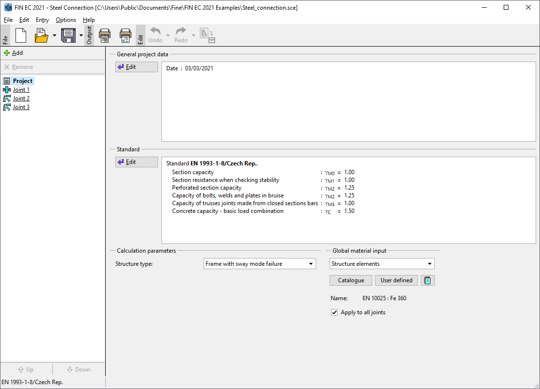 Main screen
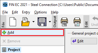
We add a new task with the help of the button "Add" at the top of the tree menu
 Insertion of a new task
We specify a name ("Column base 1") in the window "Add joint", that appears after the clicking on that button.
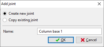 Input of task name
After the confirmation by the button "OK", the window with main joint types appears. We select column base (in the middle of the upper row).
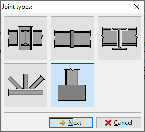 Choice of detail type
The choice of connection type follows. We select connection with end plate (left option) and confirm the choice by the button "OK".
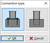 Selection of connection type
The initial geometry of the joint appears in the workspace.
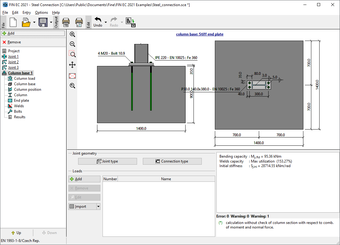 Fundamental geometry of column base
The following work is done with the help of the tree menu on the left side of the program. The structure of this menu is generated according to the specified joint geometry.
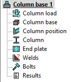 Inputs organized in the tree menu
We go through all parts from the top to the bottom and modify inputs. The connection to the left flange will be described in detail. The connection to the right flange would be solved in the same way.
On the main screen of the joint, it is possible to change the specified geometry of the joint (buttons "Joint type" and "Connection type") and specify list of loads. The load represents a set of internal forces that have to be defined for all members in the joint (column, beams). These internal forces should be resulting values of certain load combination. Therefore, they are considered as design values. Number of loads for the joint is not limited. We insert a new load with the help of the button "Add" in the toolbar on the left side of the loads table. The toolbar also contains buttons for editing and deletion of loads and also a tool for import of loads including internal forces from *.txt or *.csv file.
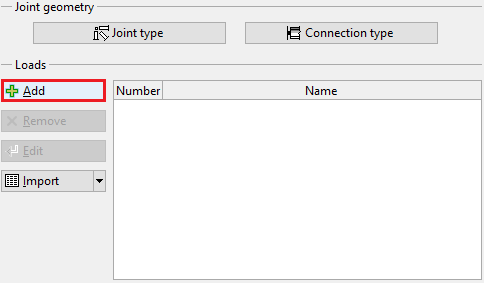 Button for input of new load
The new is specified by a name. The input has to be confirmed by the button "Add".
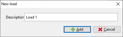 Window "New load"
As we want to add only one load, we close the window by the button "Cancel" after the input of first load.
Column load
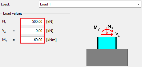
If at least one load is entered, it is possible to switch to the part "Column load" in the tree menu and specify internal forces for the column. The axial force "Nx" should be 500kN and the bending moment "My" is 60kNm.
 Input of forces
Column base
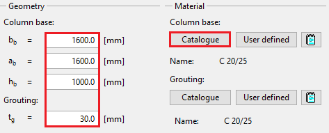
This mode contains dimensions of concrete base ("bb" - width, "ab" - length, "hb" - height) and thickness of grouting "tg". Choose the material of the column from the catalogue.
 Dimensions
Column position
The position of the column relatively to the centre of concrete base and the column pitch can be specified here. We do not change default values and go to another part.
Column
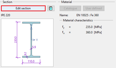
We specify the column geometry (cross-section, haunches) with the help of the button "Edit section".
 The button for edit of beam geometry
The window "Column properties" appears. Left part of the window contains input of cross-section, right part input of haunches. We change the cross-section with the help of the button "New".
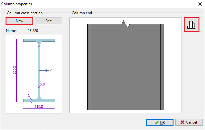 Buttons for editing cross-section and haunches
The window "Steel section" that appears after the clicking on the button contains an option to select type of cross-section. We select an option to specify arbitrary dimensions of welded cross-section (the option "Solid welded") and open the window "Cross-section editor" by pressing the button "OK".
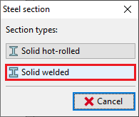 Selection of cross-section type
We enter the cross-sectional dimensions and confirm the input by the button "OK".
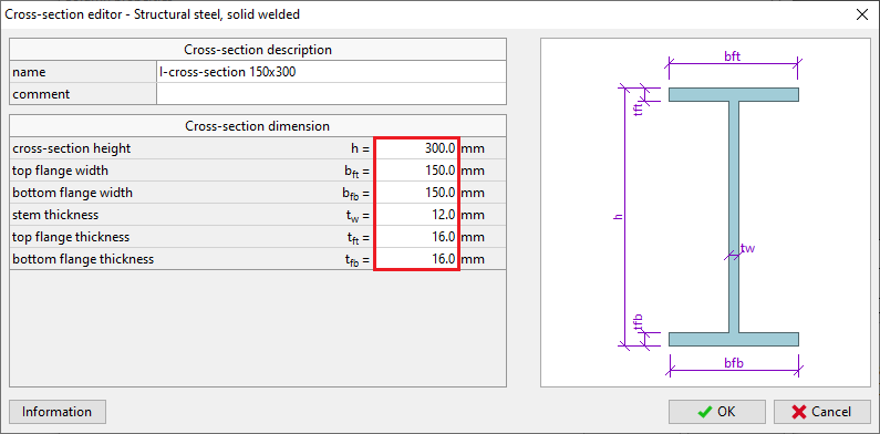 Dimensions of welded cross-section
The button in the part "Column end" opens the window "Column haunches". We select an option "Haunch without flange" and specify dimensions according to the following figure in the tab "Left haunch". As the column cross-section is symmetrical, we copy the haunch also to the right flange. We use the dedicated button "Copy to "Right flange"" in the left bottom corner for this operation.
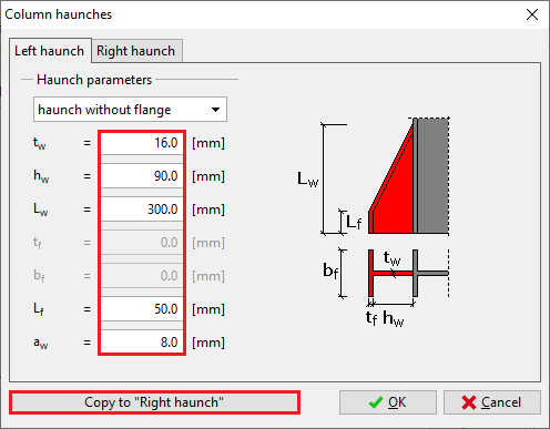 The button for copying properties
The copy of haunch properties have to be confirmed in a new window.
 Confirmation window for copy of haunch properties
End plate
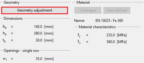
The input of end plate geometry follows. We open an appropriate window using the button "Geometry adjustment" in the bottom frame.
 The button for editing plate properties
We specify end plate dimensions "bp", "hp", "tp", position of end plate relatively to the beam edge "a1", horizontal position of bolts "w1" and vertical positions of rows. Entered values are shown in the figure below. The input can be done with the help of input lines in the left part of the window or using active dimensions in the end plate figure in the right part of the window. The input has to be confirmed by the button "OK".
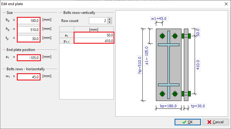 Properties of end plate
Welds
Fillet welds all round will be used for the connection of the end plate to the column. Therefore, we select weld type "Weld all around" and enter the throat thickness for flanges "aw,f" and the throat thickness for the web "aw,w". Lengths are calculated automatically according to the geometry of the cross-section. Arbitrary lengths can be defined using weld type "User defined weld".
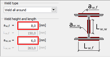 Welds properties
Bolts
The part "Bolts" contains the input of bolt type, dimensions and material. The type and dimension can be specified with the help of the button "Catalogue" in the part "Bolt type" of the bottom frame. The material can be selected using the button "Catalogue" in the part "Bolt material".
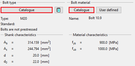 Buttons for input of bolt type and material
We select bolt type "Glued bolts in drilled sleeves" and the diameter "M24". The window has to be closed by the button "OK".
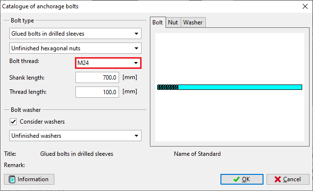 Properties of anchoring bolts
We choose the material "Bolt 10.9" in the window "Materials catalogue" and confirm the input by the button "OK".
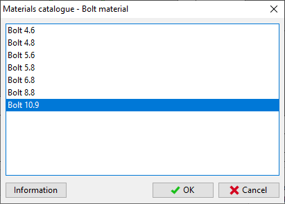 Selection of material
Results
The total results are displayed in the right part of the bottom frame. They contain maximum utilization, the decisive load and connection and also brief results for decisive load.
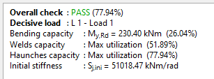 Overall results
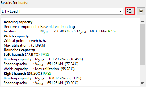
Th detailed results for particular components are displayed in the mode "Results". These results contain detailed bearing capacities and decisive components. The results can be displayed for all entered loads. Available is also an option "Zero load". In this case, maximum bearing capacities for all components are displayed.
 The button for scheme of forces in contact joint
The button on the right side of the load list (can be seen in the figure above) is able to open a scheme of contact joint with distribution of forces.
 Distribution of forces in the contact joint