Steel truss joint
Introduction
This guide shows the input of truss joint in the program "Steel Connection". A web made of two L-profiles is bolted to a joint plate.
Chord: | 2x L 120x12 |
Web: | 2x L 90x8 (X= -20mm, Y= 0, D= 100mm) |
Plate: | bp= 230mm, hp= 140mm, tp= 12mm, hp1= hp2= 15mm, aw= 3mm |
Material: | EN 10025: Fe360 |
Bolt type: | M20 4.6 |
Position of bolts: | single row, e = [40, 70, 70] mm |
Welds: | aw.1 = 3 mm, aw.2 = 3 mm, aw.3 = 3 mm |
Creation of a new joint
As general characteristics (standard, global material etc.) were already specified in the previous guide, We start directly with addition of a new joint into the existing project. We use the button "Add" at the top of the tree menu on the left side of the window. The window "Add joint" appears, it is necessary to specify a name there. The input has to be confirmed by the button "OK".
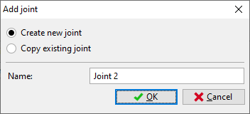 Input of joint name
The window "Joint types" appears. We select a truss joint (left option in the bottom row) and continue with the help of the button "Next".
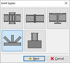 Joint type selection
The choice of connection follows. We select connection with fin plate and confirm the choice by the button "OK".
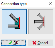 Choice of connection type
The initial geometry of the joint appears in the workspace.
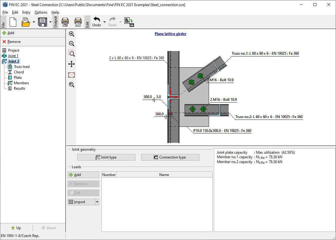 Initial geometry of the joint
The inputs for this joint are also organized into few parts, that are listed in the tree menu. As we are searching for the maximum resistance of the joint, we will skip parts "Joint 2" (list of loads) and "Truss load" (internal forces for connected webs).
Chord
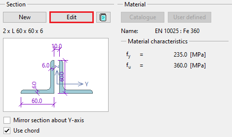
The part "Chord" contains the properties of continuous member of the joint. The input and consideration of the chord can be switched off with the help of the setting "Use chord". Unsymmetrical L-profiles can be mirrored by using the setting "Mirror section about Y-axis". We use the button "Edit" to modify the cross-section.
 Chord properties
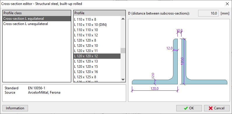
We select the profile class "Cross-section L equilateral" in the left column of the database in the window "Cross-section editor". The cross-section "L 120x120x12" should be selected in the second column of the database. The distance "D" between partial cross-sections cannot be edited, as it is selected automatically according to the plate thickness. The choice has to be confirmed by the button "OK".
 Database of cross-sections
Plate
The geometry of the plate and weld thickness can be changed in this part. We use values according to the following figure. Buttons for an input of material are disabled, as the global material specified at the beginning is used.
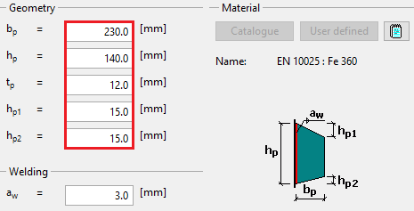 Plate properties
Workspace shows following geometry of the joint:
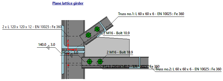 Joint geometry
Members
This part contains a list of connected webs. As we need a joint with one connected web, we have to delete one of existing members. This member has to be selected in the table (highlighted by a bold font) and after that it can be deleted with the help of the button "Remove".
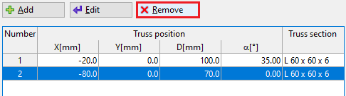 Deletion of the member number 2
The confirmation window appears, we use the button "OK".
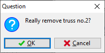 Confirmation window
Only one connected member remains in the joint. This member has a wrong position. Therefore, we have to change its position.
 Geometry of joint
For editing the member, we can use the button "Edit" above the table of members or double-click on the corresponding row of the table. The window "Member properties" contains two tabs: "Member" and "Connection". We change the position of the member with the help of input fields on the right side of the tab "Member". We also have to change the cross-section. We use the button "New" in the left upper corner of this tab.
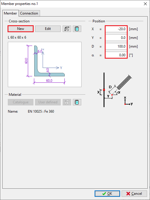 Change of member's position and cross-section
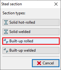
We choose type "Built-up rolled" in the next window.
The database of cross-sections opens. The type "L 90x90x8" has to be selected here.
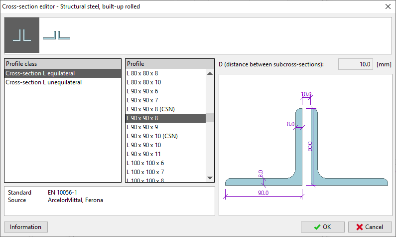 Database of cross-sections
We close the window using the button "OK".
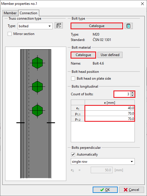
We switch to the tab "Connection" in the window "Member properties". It is necessary to increase the number of bolts to 3 and specify the distances between bolts (40,70,70).
 Position of bolts
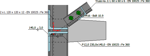
We also change the material of bolts. In the same tab "Connection" of "Member properties no.1" we use the button "Catalogue" for selection of the material and select the material "Bolt 4.6". We close the window "Member properties no.1" by the button "OK". Final geometry of the joint can be seen on the following picture:
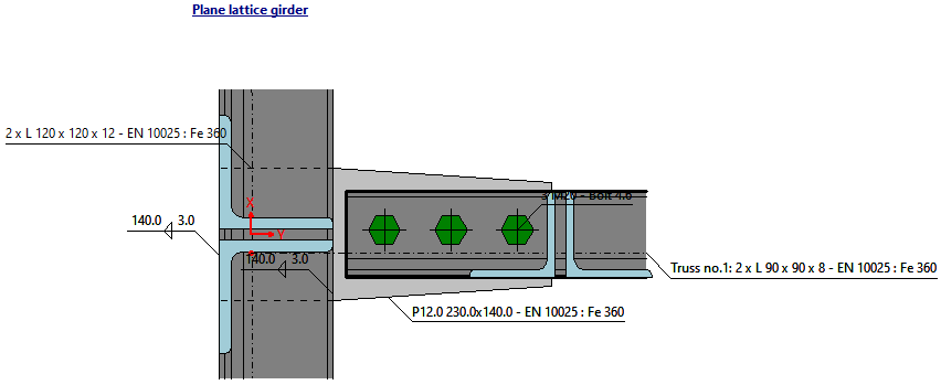 Geometry of joint
Results
The results show that the maximum resistance of the connection is 202,49 kN. The plate would have an utilization 60,17% in this case. Detailed results are available only for "Zero load", as we have not specified any load. The detailed analysis can be printed easily using the button "![]() ".
".
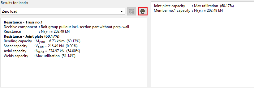 The button for printing of detailed results