Beam to column connection with end plate
Introduction
This guide shows the input of double-sided connection of beams to a column in the program "Steel Connection". The connection on the left flange of the column is designed using end plate, a beam on the right flange of the column is connected with the help of welding. The joint is a part of a structure without sway mode failure.
Beam forces: | My,Sd= 30 kNm, Vz,Sd= 100kN |
Axial force in column: | Nx,1 = 700kN, Nx,2 = 500kN |
Column: | HE 140B - EN 10025 : Fe360 |
Beam: | IPE 200 - EN 10025 : Fe360 |
Welds: | aw,f= 6mm; aw,w= 4mm |
End plate: | bp= 120mm, hp= 280 mm, tp= 12mm, a1= -70 mm - EN 10025: Fe360 |
Bolts position: | w1= 30mm, e= [35, 80, 120]mm |
Bolts: | M16 8.8 |
Starting new project
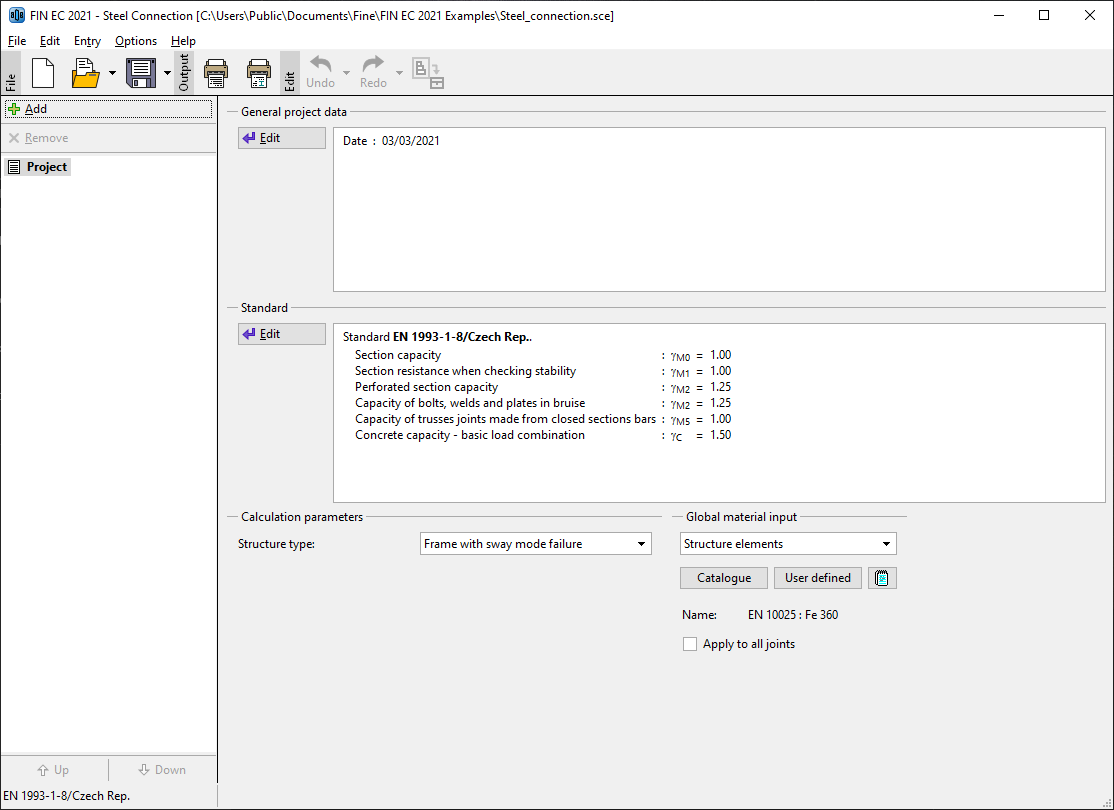
The main screen of the program contains general project information, properties of design standard and also an option to specify global material for all parts of connections.
 Basic screen of the program
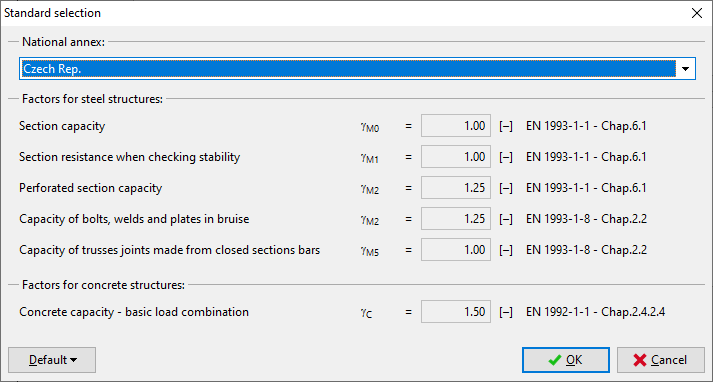
First, we select a national annex. It is necessary to click on the button "Edit" in the part "Standard" in the middle of the basic screen. A window "Standard selection" appears. Upper part contains a list box with available national annexes. National annex "User defined" contains an option to specify partial safety factor by the user in the bottom part of the window.
 Choice of a national annex
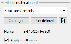
As all parts of the joint have identical material, we can use a tool "Global material input" in the right bottom corner of the window and assign this material to all parts of the connection. We select "Structure elements" in the list of entities. "Structural elements" are all steel parts of the detail (column, beams, end plates etc.) except connectors. This material will be assigned to all structural parts after ticking the check box "Apply to all joints".
 Input of a global material
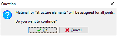
To avoid unwanted changes in existing connections, this step has to be confirmed by a confirmation window.
 Assignment of the global material to all connections
The part "Calculation parameters" contains an option to specify a structure type. This setting is important for a calculation of stiffness and classification of the connection (pinned, semi-rigid, rigid).
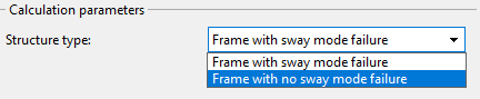 Choice of structure type
After the setting of all these parameters, it is possible to start with the input of joints. The wizard for a new joint can be launched by the button "Add" in the heading of the tree menu.
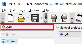 Insertion of a new joint
We specify a name ("Joint 1") in the window "Add joint", that appears after the clicking on that button.
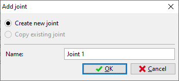 Input of a name
After the confirmation by the button "OK", the window with main joint types appears. We select beams connected to a column (left option in the upper row).
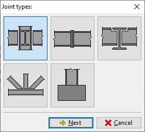 Selection of joint type
Following window contains an option to specify particular connections in the joint. New connection can be assigned to corresponding direction with the help of buttons with red "X". We have to click on the left upper button to assign a connection to the left flange.
 Selection of connection to the left flange
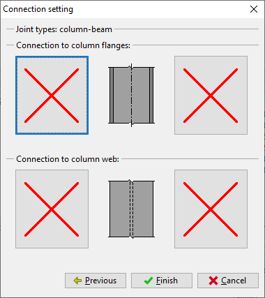
The new window "Connection type" appears after clicking on the button. Following connection types are available for this type of joint (first column is the position in the window "Connection type"):
Upper row, left |
|
Upper row, middle |
|
Upper row, right |
|
Bottom row, left |
|
Bottom row, middle |
|
We select stiff end plate (the button in the right upper corner) and confirm the input by the button "OK"
 Choice of connection type
We specify also the connection to the right flange. For this connection, we select the type "Welded connection". Following figure shows the joint with selected connections:
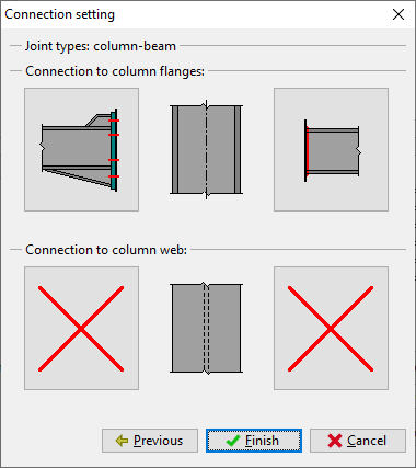 Joint with specified connections
The initial wizard has to be confirmed by the button "Finish". The fundamental geometry of the joint will be created in the workspace, the structure of the tree menu corresponds to this geometry.
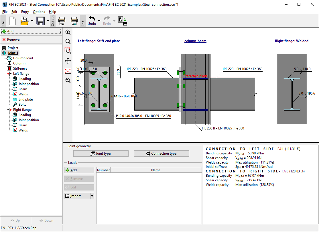 Main screen with defined geometry of the joint
Input of particular components
The following work is done with the help of the tree menu on the left side of the program. The structure of this menu is generated according to the specified joint geometry. We go through all parts from the top to the bottom and modify inputs. The connection to the left flange will be described in detail. The connection to the right flange would be solved in the same way.
On the main screen of the joint, it is possible to change the specified geometry of the joint (buttons "Joint type" and "Connection type") and specify list of loads. The load represents a set of internal forces that have to be defined for all members in the joint (column, beams). These internal forces should be resulting values of certain load combination. Therefore, they are considered as design values. Number of loads for the joint is not limited. We insert a new load with the help of the button "Add" in the toolbar on the left side of the loads table. The toolbar also contains buttons for editing and deletion of loads and also a tool for import of loads including internal forces from *.txt or *.csv file.
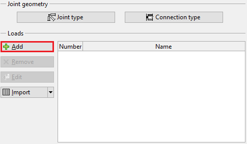 Button for input of new load
The new is specified by a name. The input has to be confirmed by the button "Add".
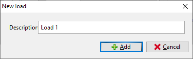 Window "New load"
As we want to add only one load, we close the window by the button "Cancel" after the input of first load.
Column load
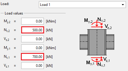
If at least one load is entered, it is possible to switch to the part "Column load" in the tree menu and specify internal forces for the column. The axial force above the joint "Nx,2" should be 500kN. As the increment due to connected beams is 2x100kN, the axial force under the joint "Nx,1" is 700kN.
 Input of forces in the mode "Column load"
The next step is an input of column geometry in the part "Column".
Column
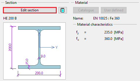
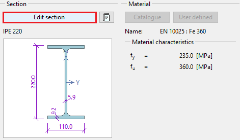
This part contains a geometry of the column (cross-section, length, material). Buttons for an input of material are disabled, as the global material specified at the beginning is used. The window for the input of column geometry can be launched by the button "Edit section" or by clicking on the cross-section in the bottom frame.
 Button for editing the column cross-section
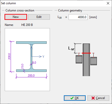
The window "Set column" is a general window for input of cross-section. The identical window is also used for input of beams etc. The distance between fundamental level of the joint and column end can be also specified here. This value is important for joints, that are affected by the proximity of column end. We change the cross-section with the help of the button "New".
 The button for input of cross-section
The window "Steel section" that appears after the clicking on the button contains an option to select type of cross-section. We select database of rolled cross-sections (the option "Solid hot-rolled") and open the window "Profiles catalogue" by pressing the button "OK".
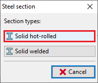 Choice of cross-section type
We select the section type "Cross-section HE" in the first column of the database and the item "HE 140B" in the second column. The choice of cross-section has to be confirmed by the button "OK".
 The database of predefined cross-sections
The part "Stiffeners" of the tree menu follows.
Stiffeners
The reinforcement of the column can be added in this part. Several types of reinforcement are organized into tabs. We specify web reinforcement on the first tab "Web reinforcement". It is necessary to change the values "aw" and "ts" both for upper and bottom stiffeners.
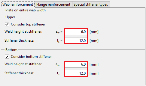 Web stiffeners
This is the last part of column properties. Now, we switch to part "Left flange".
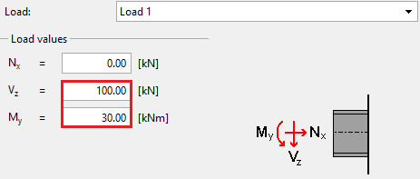
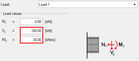
Load
Similarly to column, this part contains the input of internal forces for beam. The bending moment 30kN has to be entered into the input line "My" and shear force 100kN into the input line "Vz". Also a value for axial force "Nx" can be specified in this part.
 Internal forces for left flange
The part "Joint position" follows.
Joint position
The eccentricity of connection or pitch of beam can be specified in this part. We keep default settings and switch to part "Beam".
Beam
We specify the beam geometry (cross-section, haunch) with the help of the button "Edit section".
 The button for edit of beam geometry
This window is similar to the window with column geometry. Left part of the window contains input of cross-section, right part input of haunches.
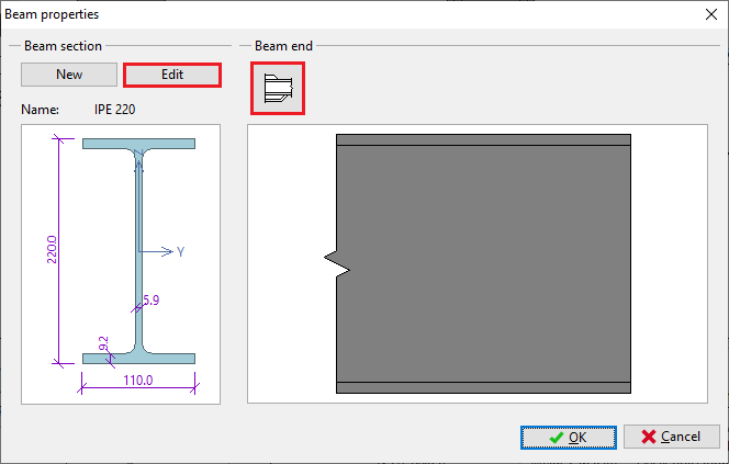 Buttons for edit of cross-section and haunch
The button "Edit" opens the database of rolled cross-sections. We change the cross-section to "IPE 200".
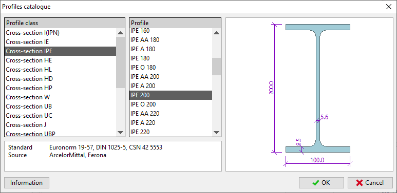 Selection of beam cross-section
The button in the part "Beam end" opens the window "Beam haunches". We select an option "Haunch without flange" and specify dimensions according to the following figure in the tab "Top haunch".
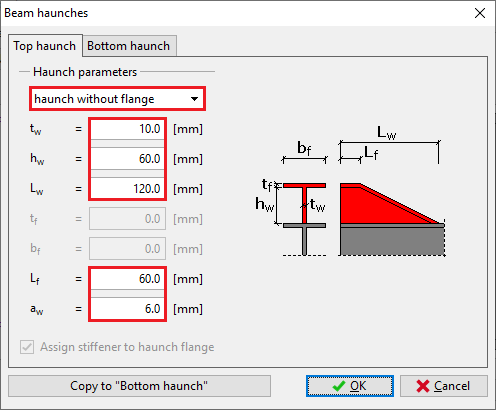 Haunch properties
We close windows "Beam haunches" and "Beam properties" by buttons "OK" and switch the tree menu into the mode "Welds".
Welds
Fillet welds all round will be used for the connection of the end plate to the beam. Therefore, we select weld type "Weld all around" and enter the throat thickness for flanges "aw,f" and the throat thickness for the web "aw,w". Lengths are calculated automatically according to the geometry of the cross-section. Arbitrary lengths can be defined using weld type "User defined weld".
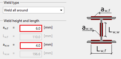 Weld properties
End plate
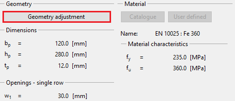
The input of end plate geometry follows. We open an appropriate window using the button "Geometry adjustment" in the bottom frame.
 Button for input of end plate geometry
We specify end plate dimensions "bp", "hp", "tp", position of end plate relatively to the beam edge "a1", horizontal position of bolts "w1" and vertical positions of rows. Entered values are shown in the figure below. Only two bolt columns can be specified for rigid end plate. Four columns are permitted for hinged end plate. The input can be done with the help of input lines in the left part of the window or using active dimensions in the end plate figure in the right part of the window. The input has to be confirmed by the button "OK".
 Geometry of end plate
Bolts
The part "Bolts" contains the input of bolt type, dimensions and material. The type and dimension can be specified with the help of the button "Catalogue" in the part "Bolt type" of the bottom frame. The material can be selected using the button "Catalogue" in the part "Bolt material".
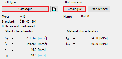 The bottom frame with buttons for input of bolt properties
We select bolt diameter "M16" and shrank length 55mm in the window "Bolt catalogue". The shrank length is an important input for the determination of shear plane. We tick on also washers under the bolt head and nut. The window has to be closed by the button "OK".
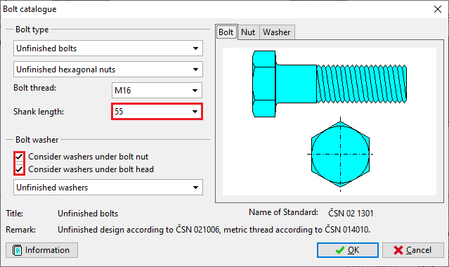 Window "Bolt catalogue"
We choose the material "Bolt 8.8" in the window "Materials catalogue" and confirm the input by the button "OK".
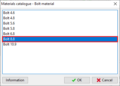 Window "Materials catalogue"
Right flange
The connection of the second beam to the right flange is similar to the already entered connection. Only properties of the end plate are missing in this case. In the part "Load", we specify the bending moment My= 30kN and shear force Vz= 100kN.
 Load for the right connection
Warnings regarding the unbalance of forces in joint should disappear after the input of these forces. No changes are required in the part "Joint position".
We select also the profile IPE 200 as the beam cross-section in the part "Beam". Finally, the weld type in the part "Welds" should be "Weld all around" and the throat thickness for flanges "aw,f" and for the web "aw,w" should be identical to the welds in the left connection.
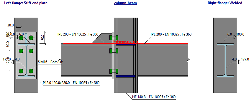 Joint geometry
Results
The total results are displayed in the right part of the bottom frame. They contain maximum utilization, the decisive load and connection and also brief results for all connections.
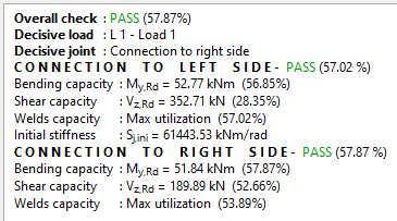 Total results
Th detailed results for particular components are displayed in the basic mode of corresponding component (nodes "Left flange" and "Right flange" of the tree menu). These results contain detailed bearing capacities and decisive components. The results can be displayed for all entered loads. Available is also an option "Zero load". In this case, maximum bearing capacities for all components are displayed.
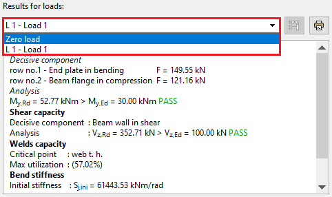 Choice of loads