Shear resistance of solid cross-sections
The shear resistance for directions z and y is calculated using expressions

Where is: | AV,z, AV,y |
|
fy |
| |
γM0 |
|
If the following expression is fulfilled for perforated cross-section,
![]()
Where is: | AV,z,osl, AV,y,osl |
|
AV,z , AV,y |
| |
fy |
| |
fu |
|
the shear resistance of perforated cross-section is calculated using expression:
![]()
kde je: | AV,z,osl, AV,y,osl |
|
fy |
| |
γM0 |
|
The minimum of Vpl,Rd and Vpl,Rd,osl is considered as the final shear resistance. If the corresponding plate of the cross-section are fixed on both ends in the perpendicular directions, the effect of local buckling is taken into consideration. The effect of the local buckling may be reduced with the help of web stiffeners. The simple post-critical method based on the chapter 5.6 is used for the buckling of walls. The local buckling is considered for slenderness greater than 69ε, where ε=(235/fy)0.5. The shear resistance including the local buckling is given by the formula
![]()
Where is: | d |
|
tw |
| |
τba |
| |
γM1 |
|
The design shear resistance VRd,z is calculated as the minimum of Vpl,Rd,z and Vba,Rd,z, the design shear resistance VRd,y is calculated as the minimum of Vpl,Rd,y and Vba,Rd,y. The buckling caused by shear isn't considered for plates supported only on one end.
![]()
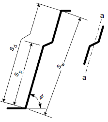
Shear resistance of trapezoidal sheeting profiles
Shear resistance of trapezoidal sheeting profiles is calculated acc. to EN 1993-1-3, 6.1.5, (6.8):
![]()
where: | fbv | is the shear strength considering buckling according to Table 6.1, |
hw | is the web height between the midlines of the flanges, | |
φ | is the slope of the web relative to the flanges. |
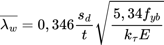
The relative web slenderness λw is for purpose of fbv obtained as follows:
- For webs without longitudinal stiffeners acc. to (6.10a):
![]()
- For webs with longitudinal stiffeners acc. to (6.10b):
| but |
|
![]()
where: | Is | is the second moment of area of the individual longitudinal stiffener about the axis a – a, |
sd | is the total developed slant height of the web, | |
sp | is the slant height of the largest plane element in the web, | |
sw | is the slant height of the web. |