Buckling
This part contains parameters of buckling and imperfection. The setting "Use imperfection" adds an and effect of imperfection l0/400 according to 5.2(9) into the analysis. Imperfection is calculated using the basic member length l0 that may be changed in the table in the bottom part of the window. The fundamental length l0 is the real length, not the buckling length.
The buckling analysis may be switched off for certain applications with the help of setting "Calculate with buckling".
The buckling analysis is affected by the creep coefficient that may be specified in the window "Creep". This window may be opened by the button "![]() ".
".
The main parameter of the buckling analysis is the method of verification. Following options are available:
Method based on the nominal stiffness |
|
Method based on the nominal curvature |
|
Simplified method based on 12.6.5.2 of the standard |
|
The imperfection and bucking parameters can be specified in tables in the bottom part of the input frame. The tables for imperfection and buckling in two directions are organized into tabs.
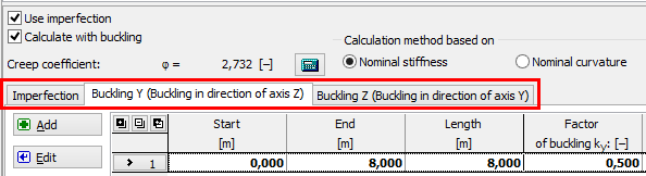 Tabs for the input of imperfection and buckling parameters
The table contains one sector along the whole member length as a default for every new member. This sector can be modified using button "Edit" or by double-click on the table row. The properties of the sector are organized in the windows "Imperfection" and "Buckling Y/Z". More sectors can be added (button "Add") for the input of different imperfection/buckling properties along the member length. The new sectors are automatically added behind the first sector according to the start coordinate called "Sector beginning". This point is automatically considered as the end of previous sector.
The particular sectors are displayed also in the active workspace. The sector lengths may be edit by using the active dimensions, double-click on certain sector launches the appropriate window for sector edit.
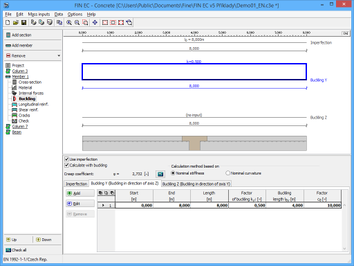 Part "Buckling" of the member design