Connection
This window contain properties of the connection between particular shafts/flanges of the built-up cross-section. These options are available:
- Not connected - no connection between particular cross-sections is considered during the analysis. The total capacity of the member is calculated as a sum of capacities of particular parts. This style will be used if the setting "Cross-section elements are joined" is switched on.
- Packs - Particular shafts of the member are connected by intermediate packs. The joints may be either nailed or glued. The distance and size of packs have to be specified. The analysis is based on chapter C.3 of EN 1995-1-1.
- Battens - Particular shafts of the member are connected by battens. The joints may be either nailed or glued. The distance and size of battens have to be specified. The analysis is based on chapter C.3 of EN 1995-1-1.
- Lattice - Flanges of the member are connected by V- or N-lattice. The joints may be either nailed or glued. Necessary inputs are distance between joints on flange and diagonal size. The number and diameter of nails per diagonal (if a diagonal consists of two or more pieces, thesum of the nails should be used). The check box "Pre-drilled holes" influences the value of slip modulus for nails. Analysis is based on C.4 of EN 1995-1-1.
Analysed spaced columns with packs or gussets columns should fulfil conditions in accordance with C.3.1(2) of EN 1995-1-1, mainly:
- The number of bays is at least three, i.e. the shafts are connected at least at the ends and at the third points.
- The distance bm between shafts isn't greater than three times the shaft thickness (for packs) or six times the shaft thickness (for battens).
- The packs length L2 satisfies the condition L2/bm ≥ 1,5, The gussets satisfies the condition l2/bm ≥ 2.
Analysed lattice columns should fulfil conditions in accordance with C.4.1(2) of EN 1995-1-1, mainly:
- there are at least three bays
- the slenderness ratio of the individual flange (node length l1) is not greater than 60
- no local buckling occurs in the flanges corresponding to the column length l1
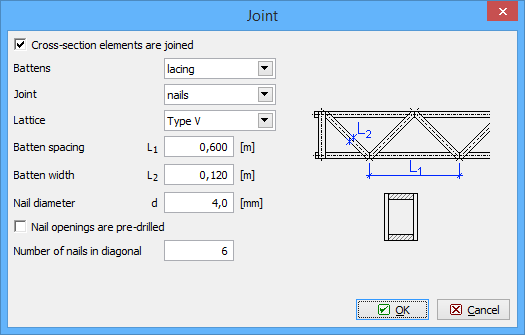 Window "Joint"