Timber truss
Task
In this example, the task is to design a symmetric roof timber truss of 13 m length and 25 degrees of the roof pitch. The truss consists of timber members of class C24 and 40 mm thickness; the spacing of the trusses is 1 m centres. The truss is subject to dead load 0.2 kN/m from both roofing and ceilings and to snow load 1.0 kN/m according to the Snow area 2 of the Czech snow map.
Setting up project
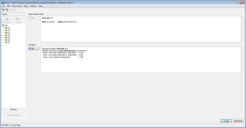
After running the program 2D, the main screen appears, consisting of the model space on the right-hand side, the control tree on the left-hand side and the input table in the bottom part. The table displays the project information which can be later used in headers and footers of the output documents. To enter or edit the project information, we can run the relevant dialog box by clicking the "Edit" button.
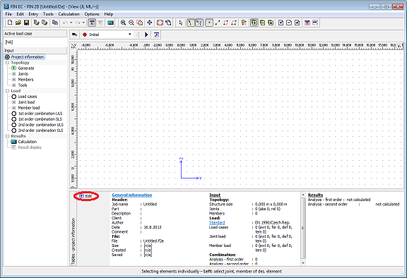 Button for running the "Project information" dialog box
In the dialog box we can enter e.g. the job title or the project author. After entering all necessary data we exit the dialog box by clicking the "OK" button.
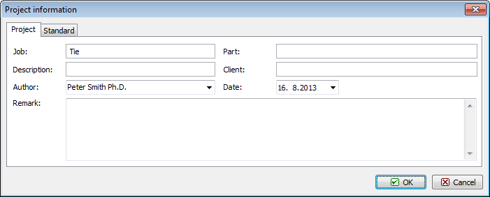 "Project information" dialog box.
Before proceeding with work we should save the job using e.g. the "Ctrl+S" shortcut. The file name is entered and the destination folder selected in the standard ‘Save as’ window.
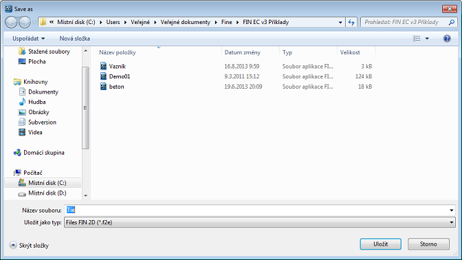 "Save as" window.
Structure generation
We can define the truss geometry either by entering individual nodes and members or we can simply make use of the Generator of 2D structures. In our example we will choose the latter approach. The generator is run by clicking the "Generate" button in the "Topology" section of the control tree.
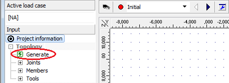 Running "Generator of 2d structures"
To generate the structure in the generator, we first click the "Wizard" button in the top left corner of the dialog box.
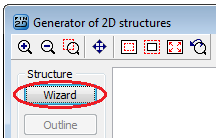 Running wizard in Generator of 2D structures
A dialog box appears enabling us to select one of the basic types of the structure. We select Basic truss types and proceed to the next step by clicking the "Next" button.
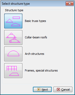 Selecting structure type
In the following dialog box, we select the desired form of the truss and click the "Next" button.
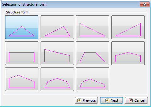 Selecting structure form
The following dialog box offers a selection of basic types of filling members’ layouts. We select the desired filling type and in the bottom left corner we switch off automatic entering of verticals by unticking the "Generate vertical members" box.
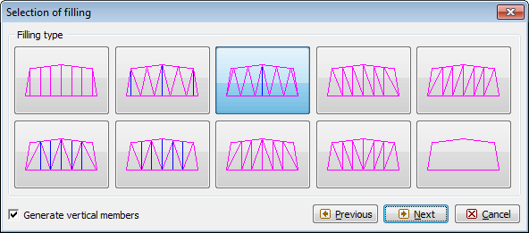 Selecting filling type
The next dialog box "Structure dimensions" enables defining the main dimensions of the truss. If we enter the pitch and the length, the program will automatically calculate the height of the truss. In the field "No. of bays on B.C." we define into how many segments the bottom chord will be divided by nodes. Additional nodes may be inserted between the main nodes of the upper and the bottom chords. In these nodes, the exact values of internal forces and deformations will be calculated and additional nodal forces can be defined. In the field "No. of intermediate joints" we can define how many nodes will be added to each segment.
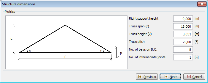 "Structure dimensions" dialog box.
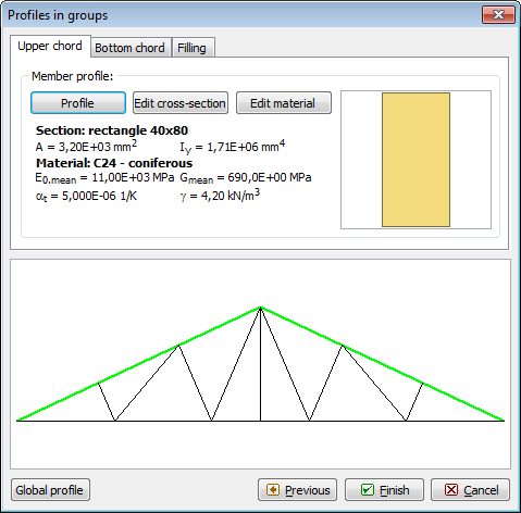
After definition of the truss dimensions, we need to specify cross-sections and materials of individual truss members. This will be done in the following dialog box "Profiles in groups" in which we can specify profiles and materials separately for the upper and the bottom chords and the filling studs by clicking the "Profile" button in the relevant tabs. However, we will use a quicker approach specifying first the material and profile for all members by clicking the "Global profile" and then only changing the profiles of the upper and the bottom chords.
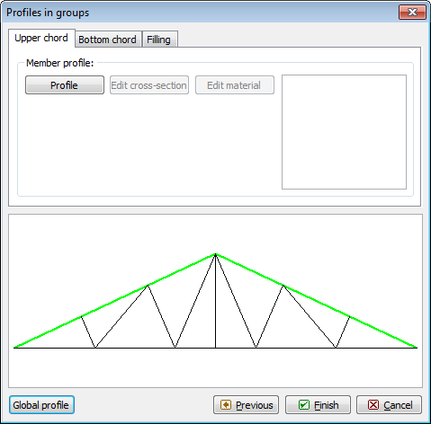 "Profiles in groups" dialog box
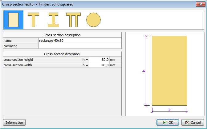
After clicking the "Profile" button, the "Cross-section editor" dialog box appears on screen. In this dialog box we select "Timber" and "Solid squared" type and define the dimensions of the rectangular profile as h = 80 mm and b = 40 mm.
 Defining cross-section dimensions
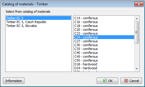
After confirming the dimensions by clicking "OK", the "Catalogue of materials – timber" dialog box appears, offering a selection of the standard timber strength classes. We select C24 and confirm by clicking the "OK" button.
 Selection of strength class
After confirming, the selected material and cross-section data appear in all three tabs of the "Profiles in groups" dialog box.
 Editing profiles of upper and bottom chords
Now we change the profiles of the upper and the bottom chords. First, in the "Upper chord" tab using the "Profile" button, we set a Pi-shaped profile and enter the dimensions.
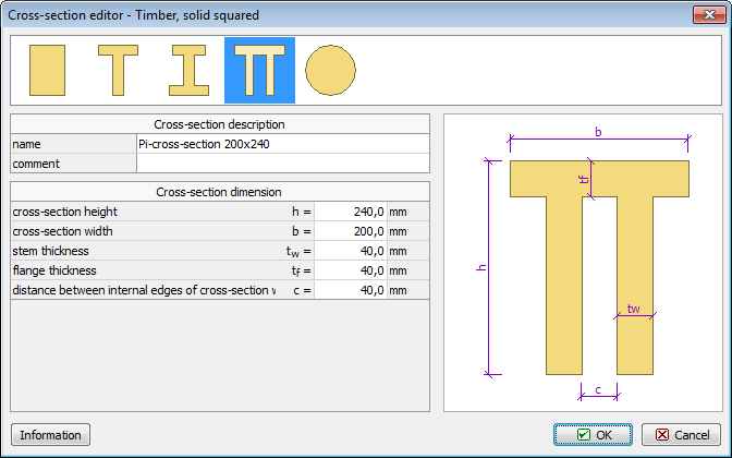 Upper chord’s cross-section dimensions
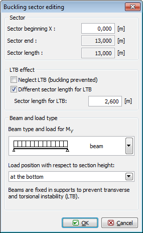
Analogically, we define a compound cross-section of the bottom chord.
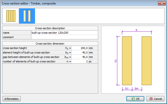 Dimensions of bottom chord’s compound cross-section
After changing the chords’ profiles we exit the "Cross-section editor" by clicking "OK". The generated truss is now displayed on screen. We can go back to any of the previous steps using relevant buttons in the "Structure" frame to the left from the model space. In the frame in the bottom of the screen, the tables for managing load cases and members are organized into tabs.
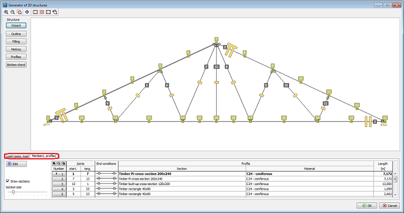 Tabs for editing load cases
We select the "Load cases, load’ tab and begin to define the load cases. Firstly, selecting "Self weight" we define a load case, which will contain automatically generated loads from the truss’s self weight. In the dialog box we can edit the name of the load case or load factors.
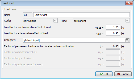 Parameters of "self weight" load case
Adding a new load case is confirmed by clicking "OK" and the loads generated from the self weight into this load case are instantly displayed in the model space. We continue with adding loads from the roofing, using the "Roofing" button. The "Roofing load" dialog box contains two tabs; the first is for specifying the load case parameters (similarly to self weight), in the second the load magnitude is defined. We switch to the second tab to enter the value 0.2 kN/m and add the load case by clicking "OK". Then we exit the dialog box by clicking the "Cancel" button.
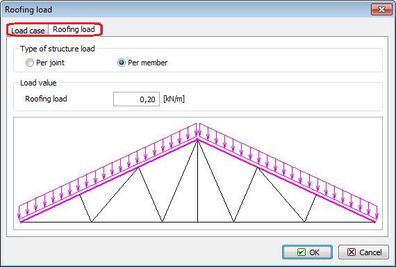 Tabs in the ‘Roofing load’ dialog box
We repeat the same procedure to define the ceiling loads.
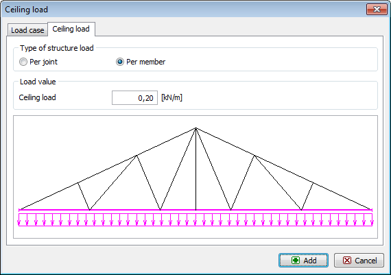 Defining ceiling loads.
For snow loads, due to the variable nature of the loading, the dialog box for the load case properties contains different data than that for the permanent loads. Short or medium term loading type can be selected, as well as the "Category" which sets the combination factors in accordance with EN 1990.
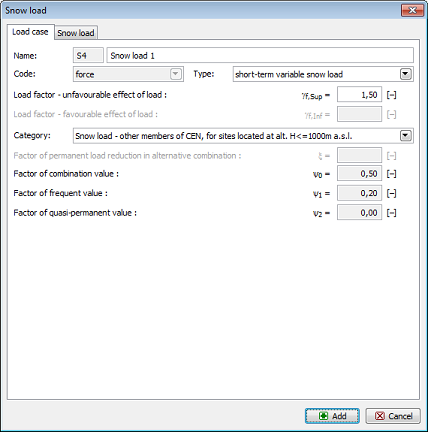 Snow load properties
In the second tab, we can define the loads separately for the left and the right side of the truss; it is possible to define non-uniformly distributed load caused by snowdrifts. The magnitude of the loading can be entered as the basic value obtained from the snow map; automatic redistribution on the inclined plane is run by ticking the "Recalculate" box. First we define the load case with uniformly distributed loads 1.0 kN/m applied to both halves of the truss; the load is applied to the structure by clicking the "Add" button. Then we can change the value s1 to 0.5 kN/m; thus we obtain a non-uniformly distributed load case which we again apply to the truss by clicking the "Add" button. Finally, we switch the values s1 and s2 to obtain a load case symmetric to the previous. We apply it by clicking the "Add" button and the "Cancel" button to exit the dialog box.
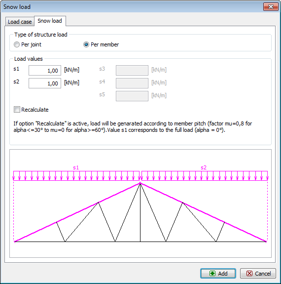 Defining snow loads
We can check and amend the defined load cases using the table in the bottom part of the Generator of 2D structures. If the load cases are correctly defined, we can insert the generated structure into the 2D program by clicking "OK". We can define structure placing and rotation in the table located in the bottom part of the main screen.
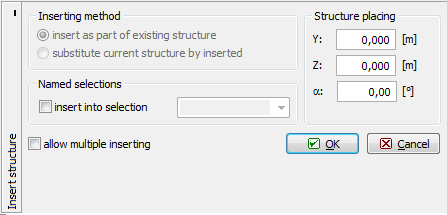 "Insert structure" table.
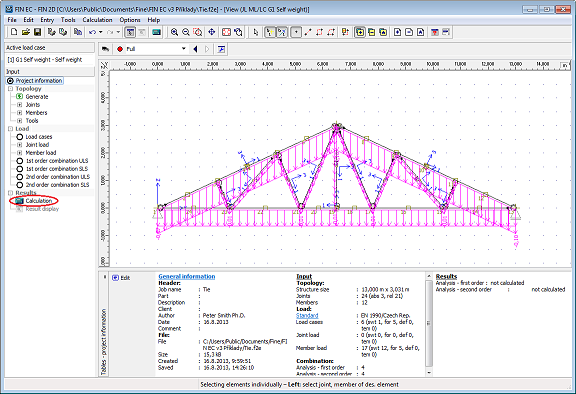
After inserting, the truss is displayed in the program’s model space. Geometry can be further edited in the "Topology" part of the control tree, load cases and loads can be edited in the "Loads" part. Only the active load case selected from the drop down list in the upper part of the control tree is displayed in the model space.
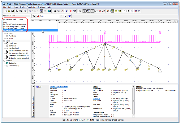 Displaying particular load cases
Definition of combinations
We can proceed to defining the load combinations which are defined separately for the ultimate and the serviceability limit states. First we define the combination for the ultimate limit state. We switch to "1st order combination ULS" in the control tree and run automatic definition of combination by clicking the "Generate" button in the table of combinations.
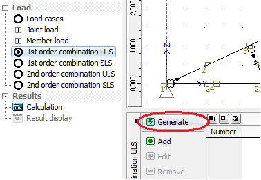 Button for automatic definition of combinations.
The automatic generation of combination is run in the "Generator of combinations" dialog box. The dialog box contains three tables. In the first, the load cases which act simultaneously are combined. In the second, we can set mutual exclusion of some load cases in one combination. The last table contains a list of variable loads which shall be considered main. In our example, we need to exclude simultaneous action of the defined snow load cases; hence we create a new exclusion group by clicking the "Add" button in the table "Excluded interaction of load cases".
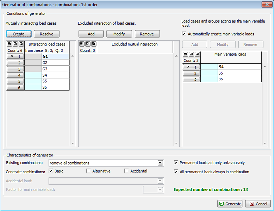 "Generator of combinations" dialog box.
In the "Excluded interaction" dialog box we select the load cases S4, S5 and S6 and confirm selection by clicking the "Add" button.
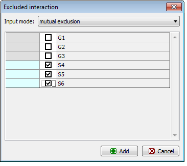 Defining mutual exclusion of load cases
After closing the dialog box a new group of mutually exclusive load cases appears in the relevant table. Thus it is guaranteed that only one of these load cases can appear in one combination.
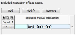 Added group of mutually exclusive load cases
Once we have finished entering data, we can create the combinations by clicking the "Generate" button. A list of the generated combinations appears in the table in the bottom part of the screen; we can add, edit or erase the combinations as necessary. We can also display the list in a comprehensive table by clicking the "Table" button.
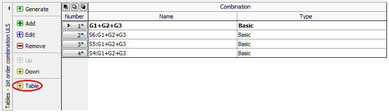 Button for running "Table of combinations"
In the "Table of combinations" we can check the generated combinations; for the active combination, a detail description including the used load factors is displayed in the bottom part of the table.
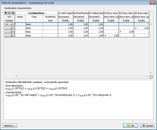 Table of combinations
Analogically we will generate the characteristic combinations switching to "1st order combinations SLS" in the control tree.
Calculation and results display
Now we can finally proceed to running the "Calculation" of internal forces by clicking the eponymous button in the control tree.
 Running calculations
The "Calculations properties" dialog box appears; we can confirm the settings by clicking "OK" after which the calculation is executed and a window with information about the calculation process displayed. After clicking the "Cancel" button, program switches automatically to post-processor.
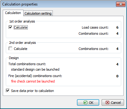 "Calculation properties" dialog box.
After finishing calculation, deformation resulting from the combination No. 1 is displayed in the model space. The program offers, apart from many other functions, a variety of settings for results displaying, e.g. enables saving views into the "Named selections" and printing all views subsequently. In our example we will show how to display the envelope of the bending moments. First we select "ULS, envelope of 1st order combinations" in the drop down list.
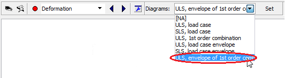 Selecting envelope display
To define an envelope of all combinations we click the "All" button in the dialog box; thus all combinations in the list on the left-hand side are automatically selected.
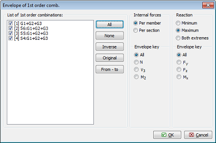 Selecting combinations for envelope
Then we run the "Cross-section display settings" dialog box and select "Bending moment".
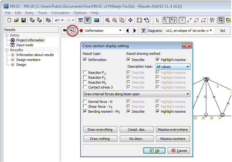 "Cross-section display setting" dialog box.
After confirming, the envelope of bending moments is displayed on the structure.
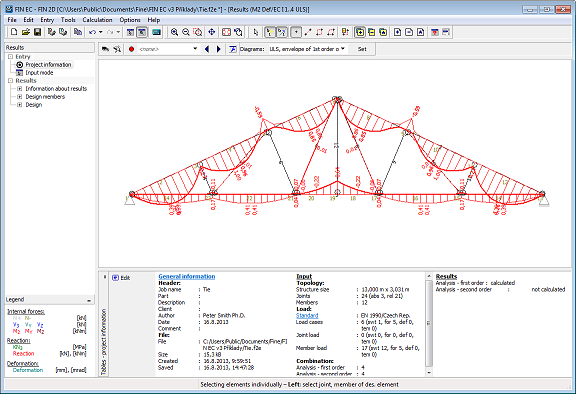 Envelope of bending moments on structure.
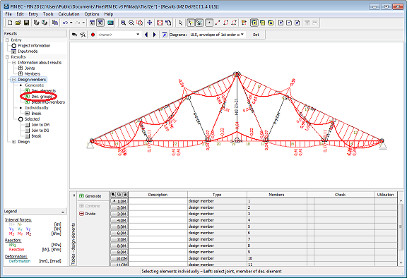
Now we proceed to design checks of the structure’s cross-sections. First we switch to the "Des. groups" in the control tree. The structure consists of total of 11 elements, representing 11 design members. The program enables merging the members into design groups so that the assessment is as quick and straightforward as possible. Members merged into a design group are checked as one member; the loading is however considered on all members separately. This approach is beneficial for instance in case when we need to check a number of concrete columns in which we want to have unified reinforcement – it is sufficient to merge all of them into one design group. To create design groups automatically, we select "Generate – Design Groups" in the control tree.
 Generating design groups
We can check in the dialog box which design groups were found by the program. If we want to create only some of the suggested groups, we can untick the "Consider all generated elements" box and then proceed only with selected design groups. In our example we will use all suggested groups, therefore we close the dialog box by clicking "OK".
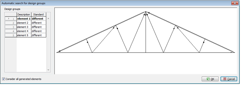 Suggested design groups
Because the orientation of particular elements vary we need to appreciate in case of which members this could cause difficulties – in our example it could be the upper chord. However; cross-sections and buckling parameters are constant along the length of the upper chords, therefore varying axes orientation should not influence the results of the assessment.
 Notice on different element’s orientation
Individual elements have been merged into 5 design groups and one design member. We can name the members and groups in the table in the bottom part of the screen.
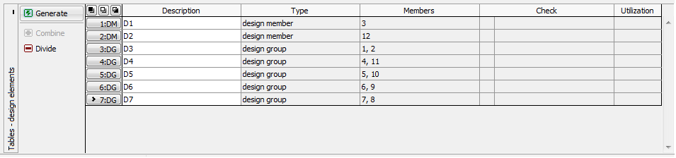 Table with entered names of design members and groups
Now we can proceed to the design itself. We select "Design" and "Timber" in the control tree and run the timber structures design program by clicking the "Run program" button.
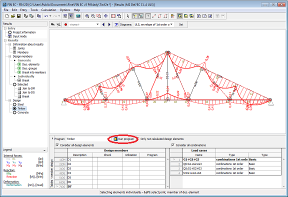 Running timber structures design program
Members design
Program 2D Timber is run with all design members and groups automatically imported.
 Design members in 2D Timber program
All data regarding geometry (members’ lengths, cross-sections etc.) and loading (internal forces distribution for all combinations) have been imported into the program. The data can be checked in the relevant sections of the control tree. We can confirm position of a selected member in the structure by clicking the "Structure preview" button.
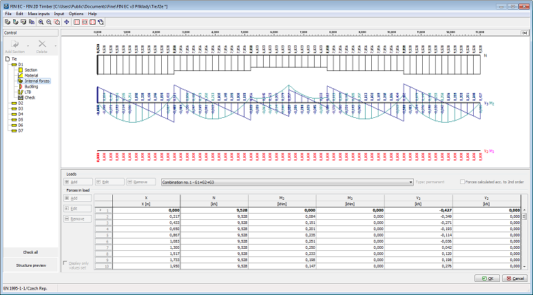 Distribution of internal forces in bottom chord
Proceeding to members design, we will demonstrate the procedure on the upper chord i.e. "D1" design group. The upper chord is subject to compression; therefore it is necessary to define the buckling parameters. In our example we assume that out-of-plane buckling is restrained by purlins at 0.6m centres. We switch to "Buckling" in the upper chords section of the control tree and run the buckling parameters dialog box by clicking the "Edit" button.
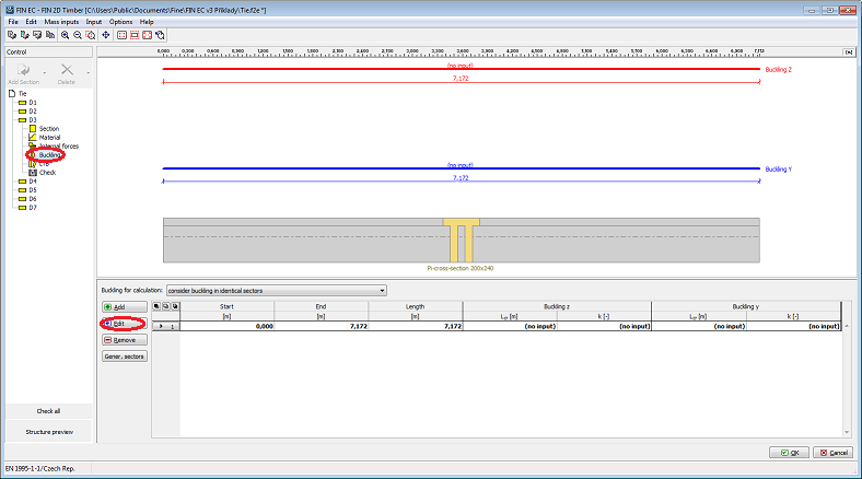 Editing buckling parameters
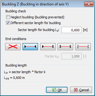
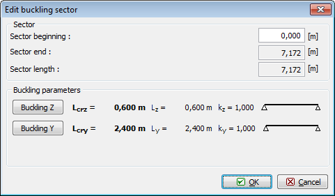
In the "Edit buckling sector" dialog box we can define parameters for out-of-plane buckling ("Buckling Z") and in-plane buckling ("Buckling Y"). For out-of-plane buckling we define simple end conditions and sector length for buckling Lz= 0.6m; for in-plane buckling we define simple end conditions as well with sector length 2.4 m. The parameters are defined in the "Buckling Z" dialog box.
 Defining in-plane buckling length
When the parameters are defined for both directions we can close the dialog box by clicking "OK".
 Defined buckling parameters
We switch to the "Check" section of the control tree and run the calculations by clicking the "Calculate" button. In the model space, the cross-section utilization curve is displayed along the length of the member; the critical section with the highest utilization is checked in the bottom right corner of the screen. If it is necessary to display detail checks in other sections, these can be added using the table in the bottom part of the screen or simply by double-clicking in the selected location of the utilization diagram in the model space.
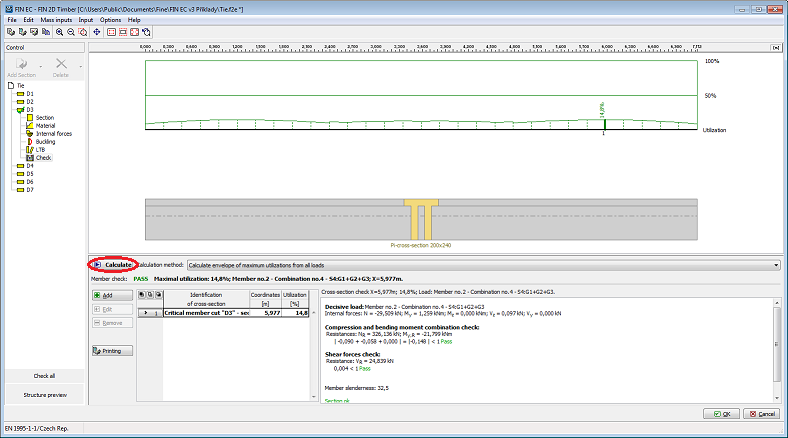 Members check
Because the maximum utilization of the member is very low, we can reduce the size of the cross-section. We switch to the "Section" part of the control tree and run the "Cross-section editor" dialog box where we can edit the cross-section geometry.
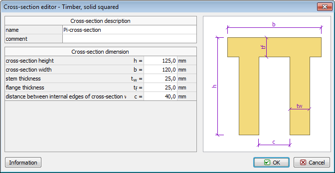 Edited dimensions of the upper chord
After editing the geometry as shown we return to the "Check" part of the control tree and re-calculate the structure, obtaining more acceptable check results.
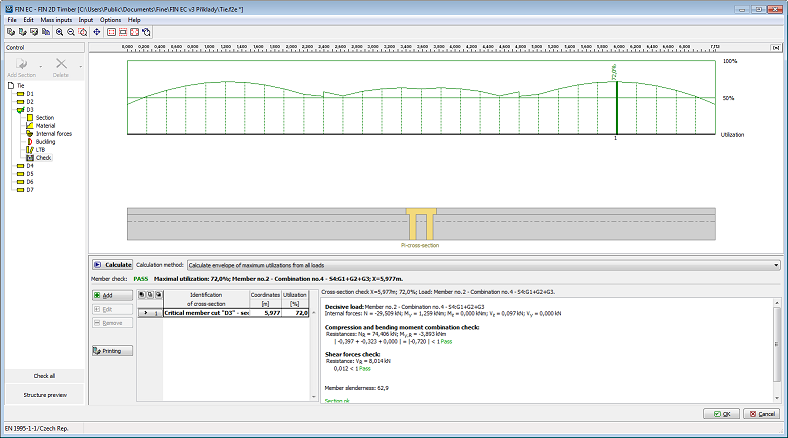 Optimized member check
Now we proceed with the "bottom chord". Because the bottom chord is in tension it is not necessary to define buckling parameters. However, we need to define lateral torsional buckling parameters as lateral and torsional stability should be checked in members subject to combination of tension and bending. We switch to the "LTB" section of the control tree and analogically to the buckling of the upper chord we define the buckling parameters for bending moment My by clicking the "Edit" button.
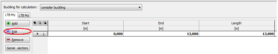 Editing buckling parameters
In the "Buckling sector editing" dialog box we define the LTB effective length and select appropriate beam and load type. We close the dialog box by clicking "OK".
 Buckling parameters
Then we switch to the "Check" section of the control tree again and carry out the members design check. Also for this member the utilization is too low therefore we edit the cross-section again.
 Editing geometry of the bottom chord
We carry out the design check again confirming more economic design of the member.
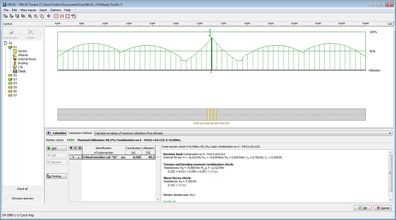 Bottom chord’s design check
Finally, the diagonals remain to be checked. Because the diagonals’ properties are almost identical, we can define the calculation parameters for all of them together. This can be done using a function in the "Mass input" part of the main menu. First we define the buckling parameters.
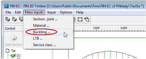 Mass input of buckling properties
Even though it would be sufficient to define the buckling parameters for the compressive members only, it is easier to assign them to all diagonals. Hence we select members D1 to D4 on the left-hand side. In the right part we tick the "Take over sector geometry from analysis" so that the program will use the actual lengths of the members as buckling lengths. Finally we define simple supports at both ends for both y and z directions. After clicking "OK" the entered parameters are assigned to all diagonals.
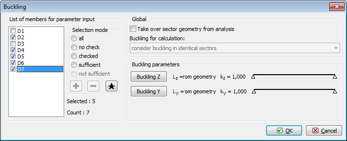 Mass input of buckling parameters
We continue with defining lateral torsional buckling parameters. Diagonals are generally only subject to axial forces therefore the LTB checks are not required; however, due to their self weight, small bending moments can occur. In such cases, the program demands lateral torsional buckling checks. In the "Mass input" section we select "LTB"; in the left part of the dialog box we again select all diagonals and from drop down list in the right part we select "do not consider buckling". Thus the influence of lateral torsional buckling will not be considered in the design checks of the selected members.
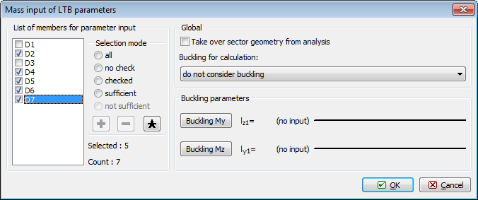 Mass input of buckling parameters
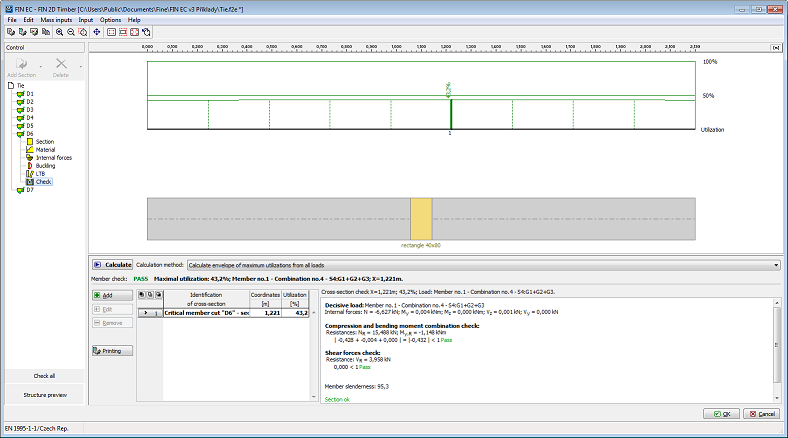
Now we can carry out the design checks for all diagonals. The diagonal D6 does not pass the buckling check, however we can increase its capacity by reducing its buckling length.
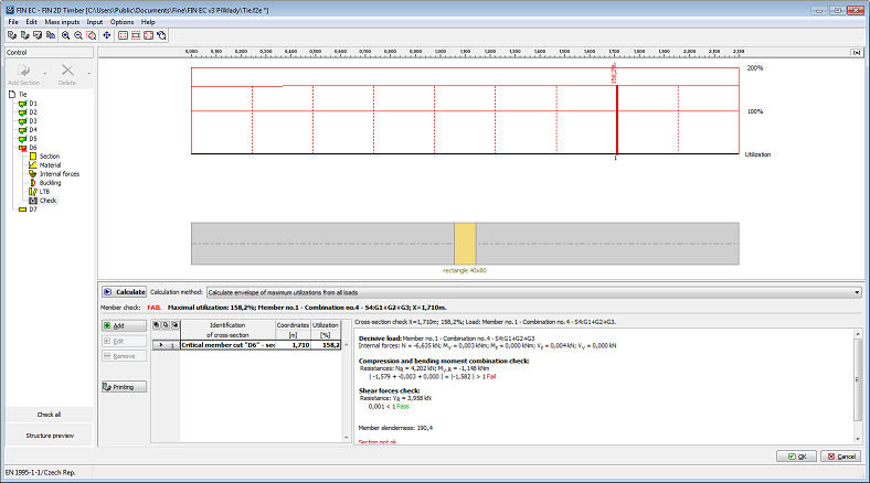 Diagonal D6 check
Therefore we design a longitudinal stiffener in the diagonal’s centre which will reduce its buckling length to half. In the "Buckling" section of the control tree we adjust the buckling length in the "Buckling Z" dialog box.
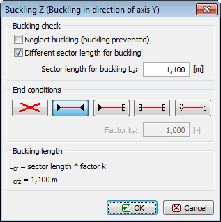 Adjusting buckling length
After re-calculating, the diagonal passes the design checks.
 Checked design members
Now all design members and groups in the structure are checked, therefore we can exit the design module by clicking "OK". Program 2D has recognized that some members were changed. Because the stiffness of individual members changed and thus different internal forces can act on some of the them, it is necessary to re-calculate the structure. The program automatically offers this option. If we select "No", the program will erase results and return to the pre-processor. In our example, we select "Yes" after which the structure is re-calculated.
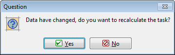 Question on re-calculating structure
After finishing the calculation, the program updates distribution of internal forces and deformations and erases the results in the design module. Therefore we run the design module again and make use of the command "Check All" located in the bottom part of the control tree. We do not have to re-define all parameters as they are saved after previous definition. The module will carry out design checks for all members and inform us about the results.
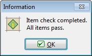 Members’ design checks results
After returning to the program 2D, members which passed the checks are marked in green and the members which did not in red. In our case, all members are marked in green; therefore the structure’s design is completed.