Member load properties
This window contains the properties of member load. The range of values differs according to the code of the active load case.
Forces and moments can be specified in load cases with code "Force". For load cases with the code "Temperature", the uniform or non-uniform warming/cooling can be specified.
The right part of the window contains the figure that shows positive orientation of inserted load.
 Window "Member load properties"
Following load types are supported:
Individual force
Type "Individual force" is the point load that acts in given position elsewhere along the member length. This load may represent e.g. reaction from supported beam. The input consists of load position and load magnitude including correct orientation.
![]() Point load in the middle of the single beam
Point load in the middle of the single beam
Individual moment
The type that is similar to "Individual force", however, the member is loaded by bending moment.
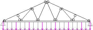
Distributed on entire member
This type represents linear load with constant value along the whole member length. This is the most common member load. The load value and orientation has to be specified for this type.
 Linear load on bottom chord
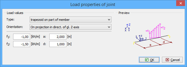
Trapezoid on part of member
Almost arbitrary linear load can be created with the help of this type. The load is given by the values at the beginning and end of load. It means, that this type may be used for input of constant, trapezoidal or triangular load. The position is given by the load length and distance from the member beginning.
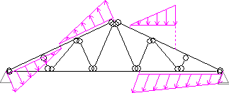 Examples of trapezoidal loads
Load orientation
Following options may be used for the definition of load direction:
Orientation along local axis 1 |
|
Orientation along local axis 2 |
|
Orientation along local axis 3 |
|
Orientation along global axes X,Y,Z |
|
On projection in the direction of global axes X,Y,Z |
|
Orientation along section axes y,z |
|
Thermal load
Thermal load may be used for considering situations, when the member is exposed to the significant changes of temperatures, that may cause additional stresses in the structure. Warming or cooling is defined as a difference of the temperature comparing to the normal state, where no additional stresses occur. The thermal load may be equal or unequal. For unequal thermal load, the temperatures on particular edges of the thermal area has to be specified. The thermal area may respect size of the cross-section (the option "Use from member section" or may be specified manually (including the position of the centre of gravity).