FIN EC software

Online Help

Tree
Settings
Program:
Language:

Anchorage

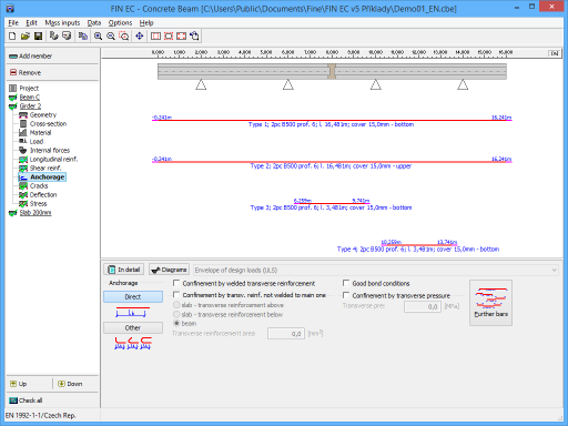
This part shows anchorage lengths for all reinforcement bars in member. Anchorage parameters can be specified in the input frame in the bottom part of the window:

Anchorage

  • The anchorage method (straight bar or other anchorage like bend, hook or loop)

Confinement by welded transverse reinforcement

  • The reduction of anchorage length in accordance with table 8.2 (coefficient α4).

Confinement by transv. reinf. not welded to main one

  • The reduction of anchorage length in accordance with table 8.2 (coefficient α3). Additional inputs are member type (the coefficient K depends on this input) and total area of transverse reinforcement

Good bond conditions

  • The anchorage conditions in accordance with figure 8.2. Good bond conditions can be considered for all members with height up to 250mm, in the bottom layer of 250mm thickness for members up to 600mm and along the whole height except upper layer of 300mm thickness for higher cross-sections.

Confinement by transverse pressure

  • The reduction of anchorage length in accordance with table 8.2 (coefficient α5)

The table with complete overview of anchorage lengths can be displayed in a new window after using the button "In detail". Anchorage lengths are also shown in the workspace. Parameters of drawing can be changed in the window "Drawing settings", that can be launched using the button "Diagrams".

Calculation and verification of stress are described in the chapter "Anchorage" of the theoretical help.

Part "Anchorage" of member design

Try FIN EC software yourself. Download Free Demoversion.