Section
Task type "Section" is suitable for the fast verification of fire resistance of the steel cross-section, that may be loaded by unlimited number of loads. General work with particular tasks of the project (addition, manipulation) is described in the chapter "Tree menu".
 Section verification
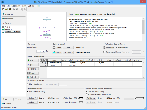
The window contains these parts:
Parameters
The member length that is used in buckling and lateral torsional buckling verifications.
Section, Material
Following buttons are placed in this part:
Section |
|
Edit |
|
Material |
|
User defined |
|
The background in described in the chapters "Cross-sections" and "Material characteristics" of the theoretical help.
Perforation, Web stiffeners
The perforation of the cross-section (caused for example by holes for connectors) and web stiffeners may be specified in this part of the tree menu. Perforation can be entered with the help of the button "Perforation", which launches the window "Perforation edit". Specified perforation reduces the cross-sectional characteristics of the member, however, the resistance of the cross-section may be higher, as the ultimate strength fu is used in the analysis. This procedure is described in the part "Perforation of cross-sections" of the theoretical help. Web stiffeners are able to increase the resistance of thin webs, where the web crippling may appears. The spacing of stiffeners has to be specified in this case. The stiffness of these stiffeners isn't checked. The assumption is, that the stiffness is sufficient. Perforation and stiffeners can't be specified for built-up cross-sections.
Battens
The connection of built-up members can be specified here. The parameters of the connection are organized in the window "Battens", that can be launched by the button "Battens".
Loads - internal forces
This part contains list of loads (combinations of internal forces and moments), that are checked during the verification. Loads can be added in the table using buttons "Add", "Modify" and "Remove". Table shows the most important information for each load (mainly internal forces and result of analysis). Load properties are entered with the help of window "Load edit".
Loads can be also imported from text or *.csv file. This feature can be used for import of large number of loads, that were calculated with the help of another structural engineering program. Import can be performed using window "Load import", that can be launched by button "Import".
Calculation parameters
The slenderness verification can be switched on in this part. The maximum permitted value of slenderness ratio has to be specified by the user. The verification is described in the part "Slenderness verification" of the theoretical help.
Buckling parameters
The buckling parameters can be specified in this part. The parameters are organized into two different directions z and y and can be specified in the window "Buckling", that can be launched by using the buttons "Buckling Z" and "Buckling Y". The main inputs (the buckling length, end conditions, basic length) are displayed on the right side of the buttons. If the axes y and z aren't the main axes of the cross-section (e.g. L-profiles), the buckling is considered in directions of the main cross-sectional axes η and ζ during the design. The buckling analysis in directions y and z may be forced by switching off the setting "Buckling to main axes η, ζ". The buckling parameters input is enabled only for tasks with at least one load, that contains compressive force. The buckling analysis is described in the chapter "Buckling resistance" and "Buckling resistance of built-up cross-sections".
LTB parameters
The parameters of lateral torsional buckling can be specified in this part. The lateral torsional buckling may be induced by bending moments My or Mz. Only lateral torsional buckling in one direction may appear for one combination of loads. As the parameters of lateral torsional buckling depend on the moment distribution, the parameters may differ for individual loads. The same buckling parameters are considered for all loads as a default. The unique parameters for individual loads may be entered after using the setting "Buckling separately for each load". If the setting is switched on, the list box with all entered loads appears on the right side of the setting. The buckling parameters has to be specified individually for all loads (the load displayed in the list box is the active one for the parameters input) in this case. The parameters are organized into two different directions z and y and can be specified in the window "LT buckling parameters", that can be launched by using the buttons "Buckling My" and "Buckling Mz". The main inputs (the basic length, beam and load types) are displayed on the right side of the buttons. The parameters input is enabled only for tasks with at least one load, that contains corresponding bending moment. The analysis of lateral torsional buckling is described in the chapter "Bending resistance".
Results
Results of the analysis for the worst load are displayed in the right upper part of the main window. Results consist of critical temperature and the fire resistance period.
The critical temperature is calculated as the temperature, for which the utilization of the member is equal to 100%. The value of critical temperature is calculated using iteration procedures. If the member fails for the temperature 20°C, this temperature is signed as a critical one and the calculation stops. As the temperature 350°C is set as a maximum one for members, that belong to the class 4, according to the designing standard, this temperature is considered as a limiting value of the critical temperature for the class 4.
Detailed results for the active load in the loads table can be displayed using button "In detail". These results are displayed in the new window, text in this window can be copied into clipboard using shortcut Ctrl+C and pasted into a document.
Analysis is described in the theoretical part of the help.