Dimensioning
The "Dimensioning" frame serves to design and verify the reinforcement of abutment cross-section - the cross-section subjected to dimensioning is selected in the combo list. The table shows the abutment forces.
Offer of cross-sections that can be verified depends on the selected load case (construction, service). The following cross-sections are available for both the construction and service state:
- Wall stem verification
- Construction joint verification - depth of construction joint from construction top edge is specified
- Wall jump verification
The service state makes also possible to verify:
- Verification of closure wall
- Verification wing - abutment - the surface surcharge due to terrain is input, for actual analysis we refer to the "Wings" section
The frame appearance is adjusted based on the selected verification methodology.
- Verification according to the factor of safety or the theory of limit states - the last column in the table allows us to input the design coefficients, which multiply the calculated forces. These forces are displayed on the desktop and are updated for every change of data and setting in the frame.
- Analysis according to EN 1997 - the last column in the table allows us to specify whether the load acting on a structure is considered as the secondary one. This is explained in more detail in the "Load combinations" section.
- Analysis according to LRFD or SIA 267 - in this case, the last column is not displayed.
The abutment is loaded either by active pressure or pressure at rest depending on the input specified in the frame "Stage settings", an active earth pressure is used when analyzing wing walls.
The way to calculate the internal forces in cross-sections is described in the theoretical part of the help.
Dimensioning of the reinforced concrete is performed according to the standard set in the "Materials and standards" tab. Verification analysis based on the standard CSN 73 6206 "Design of concrete and steel reinforced concrete bridge structures" is described here.
Several computations for various cross-sections can be carried out. Various design coefficients of individual forces can also be specified. The resulting forces are displayed on the desktop and are updated with an arbitrary change in data or setting specified in the frame. The "In detail" button opens the dialog window that contains a detailed listing of the dimensioning results.
Additional options can be found under this button ![]() - for example, exporting data to FIN EC programs.
- for example, exporting data to FIN EC programs.
Visualization of results can be adjusted in the "Drawing Settings" frame.
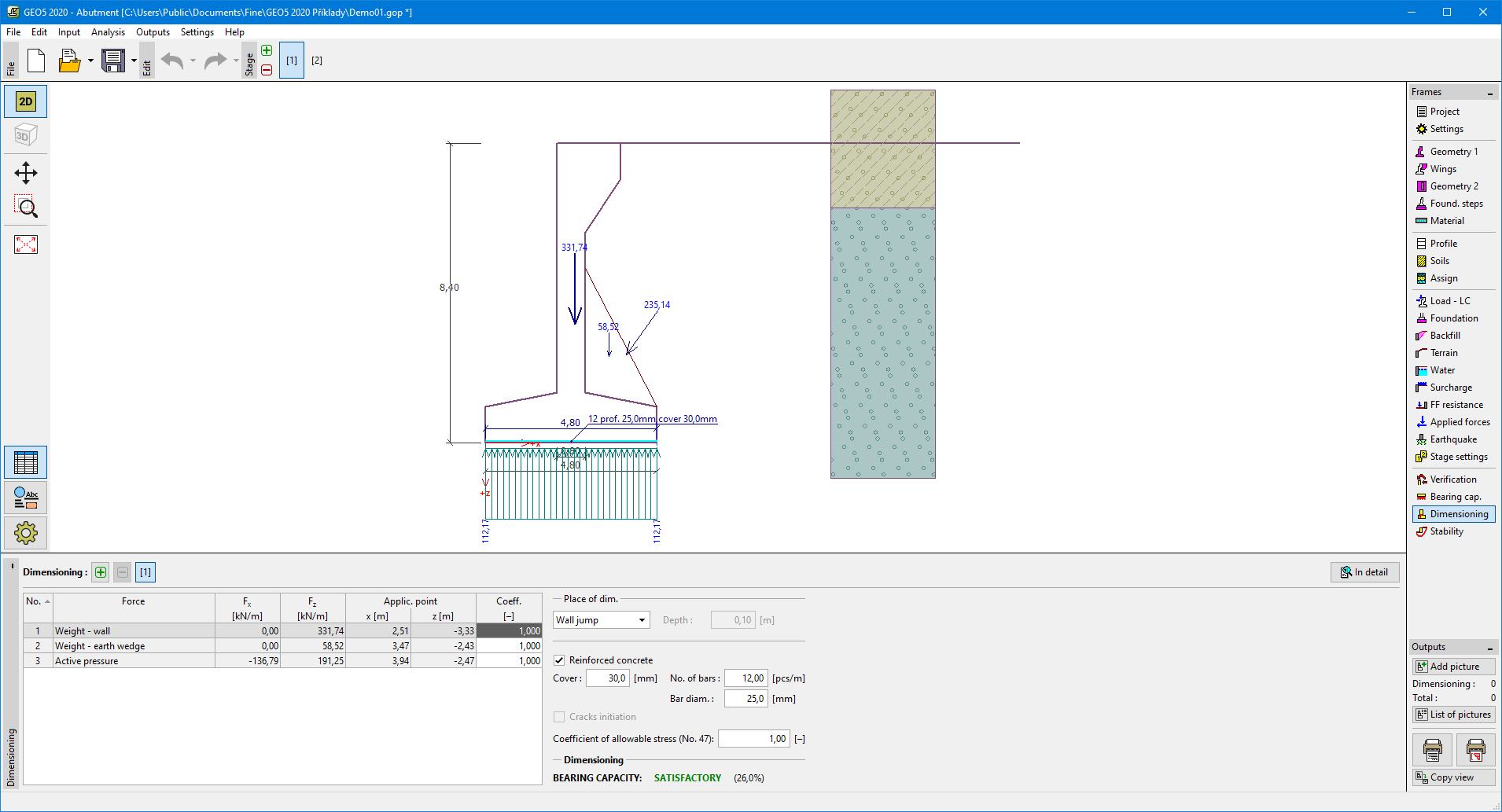 "Dimensioning" frame