Internal Stability of a Gabion
The internal stability of gabion wall can be examined with the help of:
Verification of joints between individual blocks is performed in the "Dimensioning" frame. The structure above the block is loaded by active pressure and corresponding forces are determined in the same way as for the verification of the entire wall. A loose filling is used in the analysis - not hand-placed rockfill - but its effect can be simulated using a very high angle of internal friction. It can be assumed that after some time due to the action of filling aggregate the stress in meshes will dropdown. Individual sections of the gabion wall are checked for the maximum normal and shear stress. With the help of these variables, it is possible to modify the slope of the structure face by creating terraces or by increasing the slope of the face of the wall α.
Assuming the load applied to the bottom block is schematically represented as:
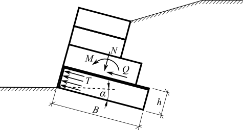 Load on the bottom block
Normal stress in the center of the bottom block is given by:
![]()
![]()
where: | N | - | normal force acting on the bottom block |
B | - | width of the upper block | |
e | - | eccentricity | |
M | - | moment acting on the bottom block | |
h | - | height of the bottom block | |
γ | - | unit weight of the bottom block material | |
α | - | gabion slope |
The pressure acting on the wall of the bottom block is determined as an increased active pressure:
![]()
![]()
![]()
![]()
![]()
where: | φd | - | design angle of internal friction of the bottom block material |
cd | - | design cohesion of the bottom block material | |
γ | - | unit weight of material of the bottom block | |
h | - | height of bottom block | |
B | - | width of upper block | |
α | - | gabion slope | |
T | - | average value of pressure acting on face of the bottom block | |
σ | - | maximal normal stress acting on the bottom block | |
Kr | - | coefficient of earth pressure at rest | |
Ka | - | coefficient of active earth pressure |
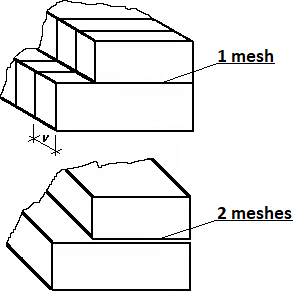
Widths of meshes of the bottom block per one running meter of the gabion wall are:
![]()
![]()
where: | Dupp | - | width of upper mesh between blocks loaded in tension |
Dtotal | - | overall width of meshes loaded in compression T | |
v | - | spacing of the vertical meshes | |
h | - | height of the bottom block |
The program allows for analysis of gabions with both simple and double mesh placed between blocks. For double meshes, the input tensile strength of mesh (frame "Material" - the "Edit material" dialog window) should be twice as large as the value assumed for simple meshes.
 Geometry of gabions