Wall Dimensioning
After computing forces acting on the structure, the program determines all internal forces in the verified cross-section (normal force N, shear force Q and moment M) and then verifies the cross-section bearing capacity employing one of the settings selected in the "Wall analysis" tab.
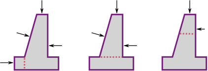
Only the forces found above the verified joint (see figure) are assumed for dimensioning. These forces are not multiplied by any design coefficients.
 Forces entering the analysis
The front jump of the wall as well as the back jump of the wall is verified against the load caused by the bending moment and shear force. Stress in the footing bottom can be assumed either constant (CSN) or linear (EC).
Assuming linear variation of stress in the footing bottom the distribution of stress is provided by:
![]()
![]()
or when excluding tension:
![]()
where: | e | - | eccentricity of the normal force N |
d | - | width of the wall foundation | |
N | - | normal force acting in the footing bottom (see verification according to limit states or factor of safety, respectively) |
Bending moment and shear force are determined as reaction developed on the cantilever beam as shown in the figure:
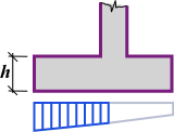 Internal forces acting on wall jump
Verification of the back jump of the wall (top tensile reinforcement in the wall jump, respectively) is performed only in some countries and usually is not required. The programs "Cantilever wall" and "Reinforced wall" allow in version 5.5 for designing the reinforcement in the back jump of the wall. The cross-section is then assumed to be loaded by the self-weight of structure, earth wedge, surcharge, anchorage force, and the force associated with the contact pressure in the soil. Forces due the pressure are accounted for only if having a negative impact. Forces introduced by the user are not reflected at all.
The cross-section is checked against the load caused by the bending moment and shear force.