Verification according to EN-1994-1-1
Standard EN 1994-1-1 refers to standards EC2 and EC3 when checking the concrete cross-section reinforced by the steel section. Partial bearing capacities of the steel section are calculated according to EN 1993-1-1 and partial bearing capacities of the concrete cross-section are calculated according to EN 1992-1-1, resp. EN 1992-2.
Check for shear
Shear bearing capacity of cross-section is given by:
![]()
where: | Vpl,a,Rd | - | design shear resistance of steel cross-section |
VRd,c | - | design shear resistance of the concrete part |
Vpl,a,Rd is defined according to EN 1993-1-1, chpt. 6.2.6 as:
![]()
where: | AV | - | shear area of steel cross-section |
fyd | - | design steel yield stress |
VRd,c is defined according to EN 1992-1-1, chpt. 6.2 as:
![]()

where: | fck | - | characteristic compressive strength of concrete |
k1 | - | coefficient with recommended value 0,15 | |
σcp | - | compressive stress in concrete | |
bw | - | cross-section width | |
d | - | cross-section height |
Design shear resistance is checked according to:
![]()
Utilization is given by:
![]()
If the shear utilization value is greater than 50%, further compression and bending checks are expected with the reduced design strength of steel (1-ρ)fyd on those parts of the steel cross-section that transfer the shear. Reduction coefficient is given by:
![]()
Check for compressive
Compressive resistance is calculated according to EN 1994-1-1, chpt. 6.7.3.2. The calculation considers effect of design strength reduction of steel due to shear stress. For concrete cross-section out off the steel section, reduced concrete stregth is assumed. Full concrete strength is calculated in the part where concrete fills closed steel section. Compressive resistance of cross-section is calculated as:
![]()
where: | Aa | - | area of steel cross-section |
ρ | - | strength reduction coefficient due to shear | |
AV | - | shear area of steel cross-section | |
fyd | - | design steel yield stress | |
A1,c | - | concrete area out of steel cross-section | |
A2,c | - | concrete area inside steel cross-section | |
fcd | - | design compressive strength of concrete |
Design resistance for compression is checked according to:
![]()
Utilization is given by:
![]()
Check for bending
The bending resistance of cross-section is determined from the interaction diagram in accordance with EN 1994-1-1, chpt. 6.7.3.2, article (5). The limits of interaction diagram are compressive resistance Npl,Rd and bending resistance Mpl,Rd. It is assumed that the concrete does not act in tensile and the stress distribution according to theory of plasticity. The scheme for determining the moment Mpl,Rd is shown in the figure below. The reduced concrete strength 0.85*fcd is assumed on the concrete part out of the steel section and full strength fcd is assumed for concrete inside the steel section. The reduced strength of the steel (1-ρ)*fyd is assumed on the parts of steel section that transfer the shear and other parts are considered with full strength fyd. Using the default values Npl,Rd and Mpl,Rd the interaction diagram is calculated and the corresponding value of bending resistance Mpl,N,Rd is determined for the applied normal force N.
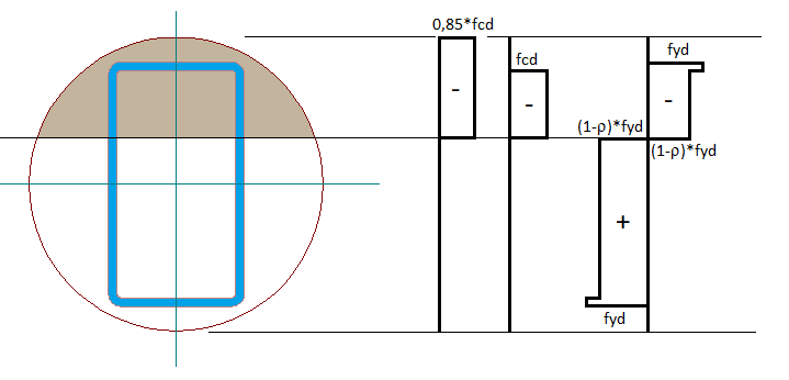 Scheme of bending resistance determination Mpl,Rd
Design resistance for bending is checked according to:
![]()
Coefficient αM has a value of 0.9 for steel yield stress fy < 400 MPa and a value of 0.8 for steel yield stress fy ≥ 400 MPa.
Utilization is given by:
![]()