Dimensioning
In the frame "Dimensioning", it is possible to display an envelope of internal forces and displacements from all analyses (stages of constructions). Normally, the envelope is constructed from the results of all construction stages, however, it can only be created from the selected stages. The "Modify" button opens the dialog window "Construction stage selection", where it is possible to select the constructions stages that are used to generate the current envelope (by pressing corresponding buttons).
The maximum values of calculated internal forces (bending moments and shear forces) and the magnitude of displacement are displayed at the bottom part of the frame.
The program allows us to dimension reinforced concrete, steel and timber, plastic, or combined cross-sections (by checking the option "Check cross-section"). For a more detailed design of reinforcement in concrete cross-section, it is possible to divide the structure into sections which are then assessed separately.
When checking the cross-section, it is possible to input the reduction coefficient of bearing capacity, which reduces the overall bearing capacity of a cross-section. When performing the analysis with the reduction of earth pressures this coefficient should be considered 1.0. For analysis without earth pressures reduction (to ensure a realistic behavior of a sheeting structure), it is necessary to increase the calculated forces, by adopting a coefficient greater than 1.0 (For EN 1997 is the value in interval 1.35 - 1.5).
For a reinforced concrete wall, standard vertical reinforcement can be specified or steel mesh can be selected from the available catalog.
For dimensioning of steel cross-sections, it is possible to assume influence of normal force in these ways:
- normal forces - do not consider: program doesn't consider influence of normal force.
- normal forces - from nearest anchor: program assumes maximum value of local normal force near the anchor as N = F*sin α, where α represents slope of the anchor
- normal forces - sum of all anchors: program adds influence of normal force from input anchors as the sum of influence of all anchors.
- normal forces - input: user-defined value of normal force N
The frame allows us to perform a larger number of analyses pro dimensioning of a cross-section. The "In detail" button at the right part of the frame opens the "Dimensioning" dialog window to show detailed results.
Additional options can be found under this button ![]() - for example, exporting data to FIN EC programs.
- for example, exporting data to FIN EC programs.
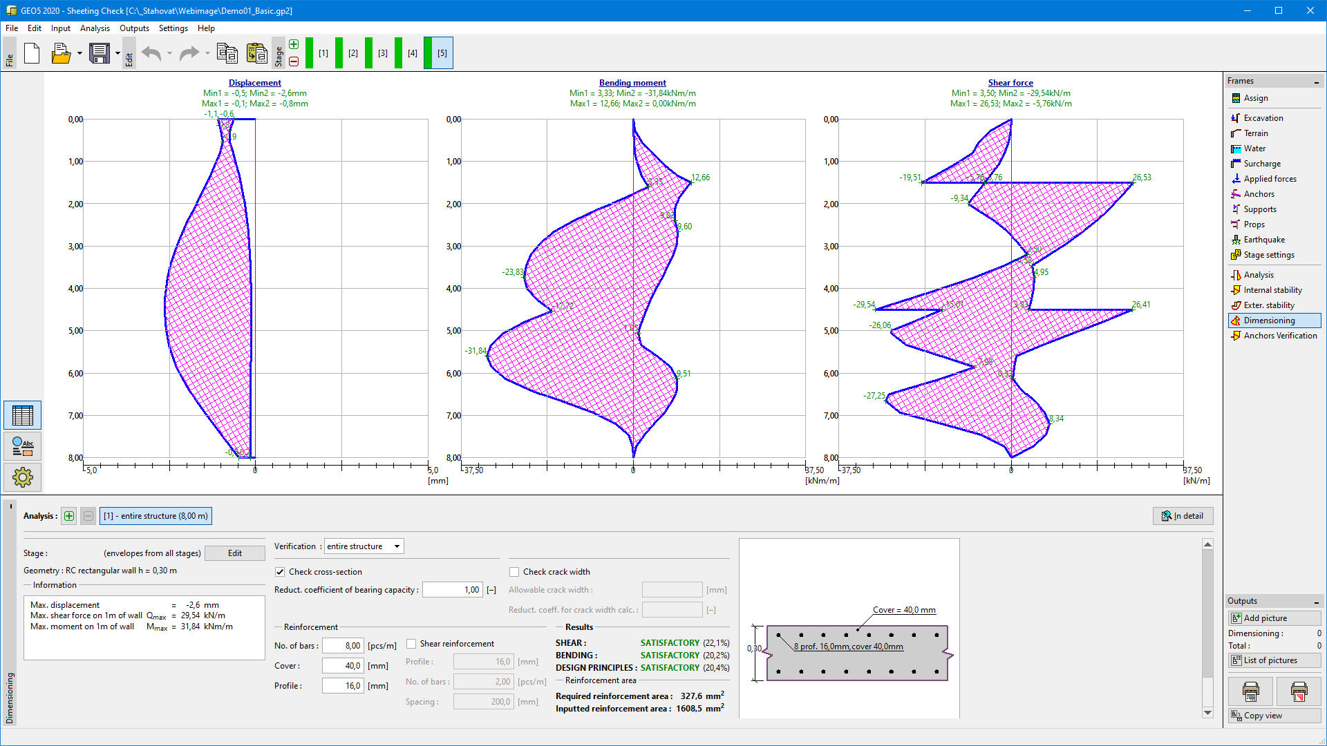 Frame "Dimensioning"