ITF Method (Imbalance Thrust Force Method)
The ITF method is a limit state method. It builds upon the equation of equilibrium of forces acting on individual blocks and does not consider the moment equation of equilibrium. The bases of the method and adopted assumptions are evident from the following figure.
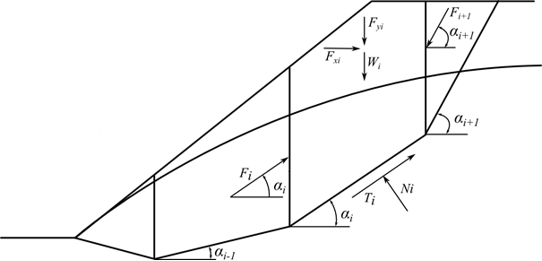 Fig. 1 Forces acting on a block - ITF Method
Consider the following assumptions concerning the forces acting on the block:
where: | Wi | - | weight of the ith block, the weight of a part of the block below the groundwater is determined from the saturated unit weight of soil γsat |
Fyi | - | represents the remaining vertical load acting on the block | |
Fxi | - | represents the remaining horizontal load acting on the block | |
Fi, Fi+1 | - | forces acting between blocks along directions given by angles αi and αi+1 |
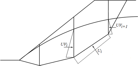 Fig. 2 Scheme of pore pressure action on the block
Ui | - | pore pressure resultant on slip surface segment | |
UVi,UVi+1 | - | pore pressure resultants on dividing planes between blocks |
The forces UVi and UVi+1 are included in the horizontal forces Fxi.
The force equation of equilibrium in the direction normal to the segment of the slip surface provides:
![]()
The forces on the segment of a slip surface are related by
![]()
where: | φi | - | angle of internal friction of the soil |
ci | - | soil cohesion | |
li | - | length of the slip surface segment associated with the ith block |
The force equation of equilibrium in the direction of the ith segment of the slip surface (given by angle αi) yields the force Fi acting between blocks in the form:
![]()
Introducing Eqs.(1) and (2) into Eq. (3) provides:

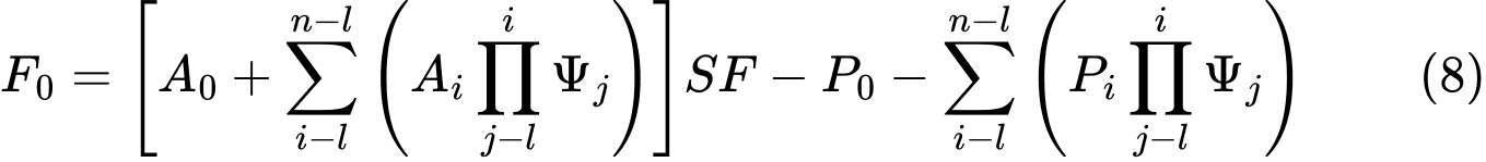
and after some formal algebra, we arrive at the resulting form of the equation of equilibrium as:

The equilibrium condition will be fulfilled by introducing the factor of safety SFS into the analysis such that the strength parameters of a given soil c and tanφ are divided by this value. Eq. (4) then becomes

Eq. (5) then gives the searched factor of safety SF through the process of iteration. This process proceeds such that the force Fn equal to 0 kN is applied at the highest (end) point of the slip surface. The forces Fi acting in between blocks are determined for a given value of the factor of safety SF from Eq. (5). This step is repeated for various values of SF until we find such SF for which the force F0 at the slope base becomes equal to 0 kN. No tension is assumed along the slip surface. If the equilibrium condition requires the value of normal force Ni being negative, which means that the soil is loaded in tension, then the value of this force is set equal to zero in the next iteration step and the shear force Ti acting on a given segment is determined based on the soil cohesion only.
The ITF method is quite sensitive with respect to the shape of the slip surface. In case the slip surface contains sharp segment discontinuities the resulting factor of safety is generally larger when compares to reality. It is recommended that the slope difference between adjacent segments of the slip surface be less than 10°. This is checked automatically by the program and if the slope difference is found greater the programs prompt a warning that the results might be overestimated. This is usually not the problem of a circular slip surface but should be kept in mind in case of polygonal slip surfaces.
ITF Method - explicit solution
The explicit solution of the ITF method assumes a different way of introducing the factor of safety into the analysis. The mathematical solution then does not require iterations and the resulting factor of safety is calculated directly in one step. With this approach, the resulting factor of safety is typically higher which may the solution totally devalued, particularly in cases concerning polygonal slip surfaces with large slope differences of adjacent segments.
The solution exploits Eq. (4) to which the factor of safety SF is introduced such that it multiplies the active components of forces, i.e. the components acting in the sliding direction. The equilibrium condition then becomes :

For lucidity, we introduce the component of active forces as:
![]()
and next to the component of passive forces as:
![]()
and an auxiliary function:
![]()
Eq. (6) can then be written in more compact form as:
![]()
The next step assumes the known force Fn=0 to provide expressions of forces between blocks F in the form:
![]()
![]()
![]()
Etc….
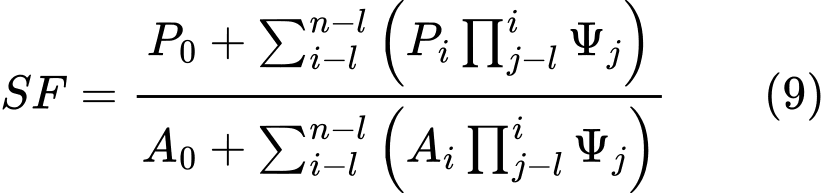
And since the force on the bottom origin of the slip surface should be equal to 0 kN, we get the final form of the factor of safety SF as: