Mesh Generation
The frame "Mesh generator" serves to define the basic setting to generate mesh (element edge length, mesh type, mesh smoothing) and to view information about the generated mesh (right part). The "Error analysis" button allows for visualization of error listing in the right part of the frame (list of problems the structure has).
Information about the resulting mesh, including warnings for possible weak points in the mesh, is displayed in the right bottom window.
An arbitrary part of the slab specified by lines (segments, arches and circles) can be meshed. The slab can be formed by one or more macroelements all having a constant thickness and identical material properties and may contain an arbitrary number of openings. In addition, it is possible to introduce internal points and lines which are then considered as mesh nodes and edges. The joints along lines and inside macroelements allow for mesh refinement, which is characterized by the required length of element edges in the center of the refinement and by the refinement radius. The user may choose either a purely triangular mesh or a hybrid mesh consisting of both triangular and quadrilateral elements. The meshing algorithm is based on Delaunay triangulation enhanced by several methods to modify and optimize the finite element mesh. The mesh nodes are automatically renumbered to minimize the computational effort.
Properly generated finite element mesh is the stepping stone for obtaining accurate results. Optimal are equilateral triangular and square quadrilateral elements. The program contains a built-in automatic mesh generator considerably simplifying this task. The basic mesh density is specified in the "Mesh generator" window. Refining the mesh increases accuracy of the results. However, high mesh density considerably slows down both the solution and subsequent visualization of the results. The goal is thus to create an optimally refined mesh - this strongly depends on user’s experience.
Thanks to the efficiency of the mesh generator, there is no problem adjusting input parameters until obtaining an optimal mesh. The mesh quality is further maintained with the help of a built-in smoothing algorithm, which can be turned off. The actual analysis step is extremely fast even for relatively dense meshes.
The following procedure to generate the finite element mesh is recommended:
Correctly generated finite element mesh is the major step in achieving accurate and reliable results. The program FEM has an automatic mesh generator, which may substantially simplify this task. Nevertheless, certain rules should be followed when creating a finite element mesh:
- | First, a uniform mesh linked to the slab thickness (1-5 multiple of its thickness) is generated throughout the slab. |
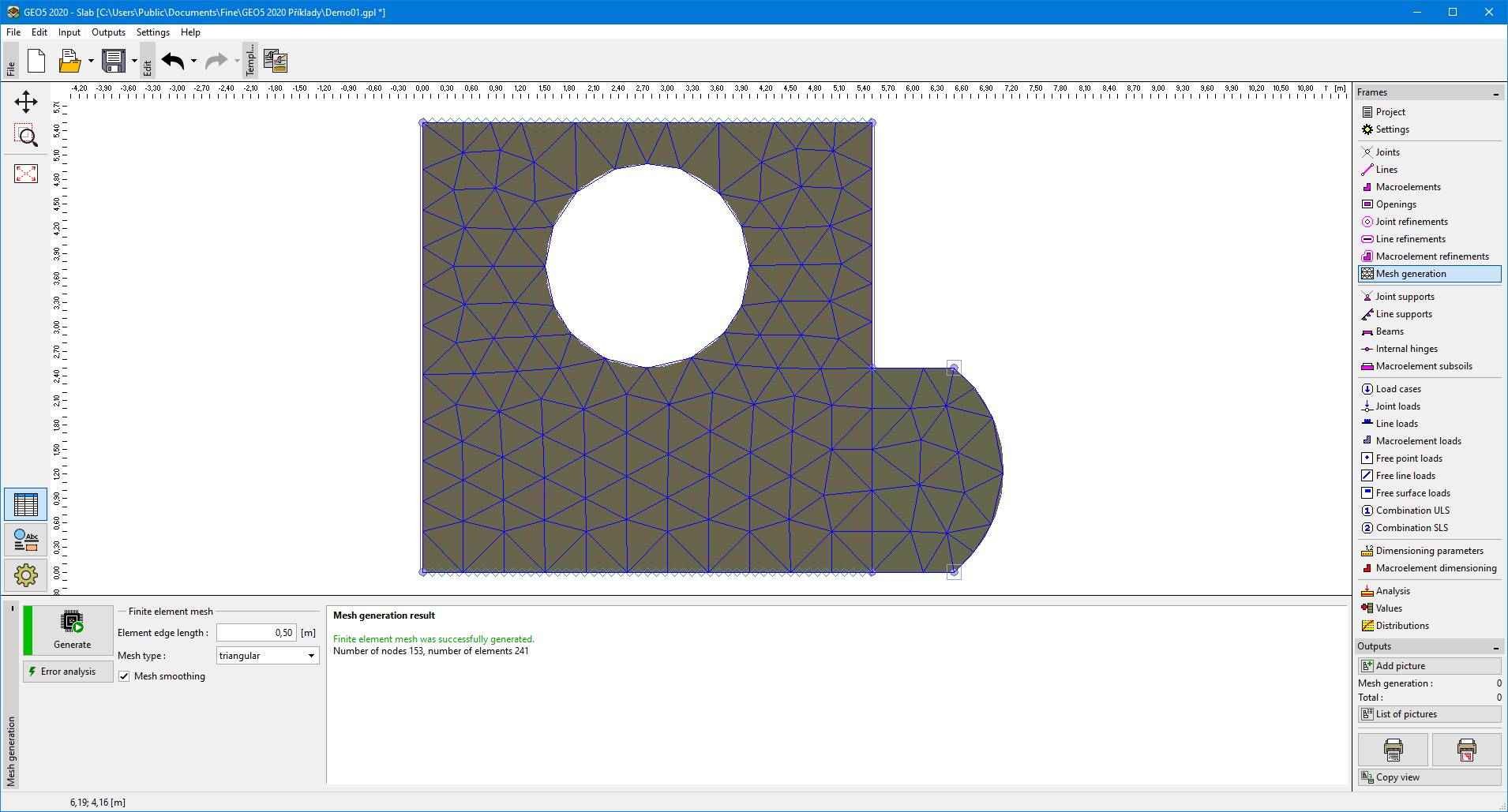 Frame "Mesh generation" - a mesh with no local refinement
- | The finite element mesh should be sufficiently fine in the locations where large stress gradients are expected (point supports, corners, openings, etc.). The mesh refinement can be specified around individual joints, lines and on the macroelements. Its radius should be at least 2-3 multiple of the density assumed in the center of the refinement and both values (density, radius) should be reasonable with respect to the refinement prescribed for the neighboring regions. This assures a smooth transition between regions with different mesh densities. Singular lines should be tackled in the same way. |
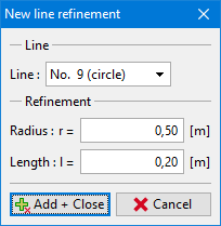 Defining mesh refinement around a circular line
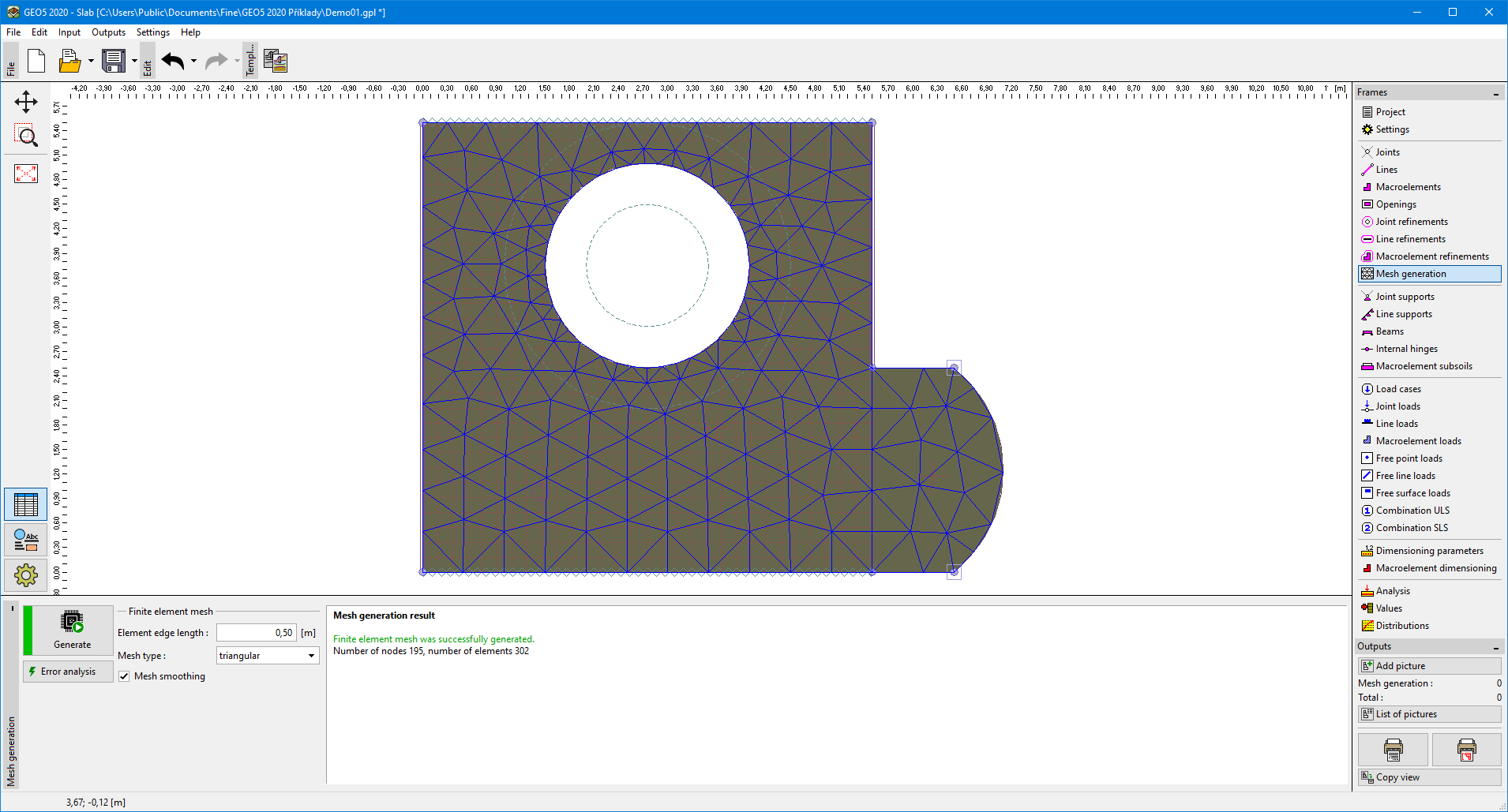 New mesh after refining the original mesh around a circular line